|
Little Nipper 64 6AN7 Converter Valve
|
|
|
|
|

|
Location: Central Coast, NSW
Member since 18 April 2014
Member #: 1554
Postcount: 215
|
Please NOTE! I had made few errors through out this post..one being resistor Value and another Valve type
These should be 4K7 and 6AV6
not to mention mistaken ID of a component lagre 22K resistor
I leave them for the integrity of the flow of the thread
--------------------------------------------------------------------
Hi All
Well sadly real life or rather people passing and a funeral has taken me away again..along with other things that aint so great in life
OK So the other nipper's on the back burner till I get a Transformer
But I have another (that the transformer works ok in)
I have replace the Electros with 450V 22uF...yeah the cheapies but in time I will probably put in better quality Caps..just they are not cheap and better to get it operational first
I have checked resistors and recapped this one but I am stuck!
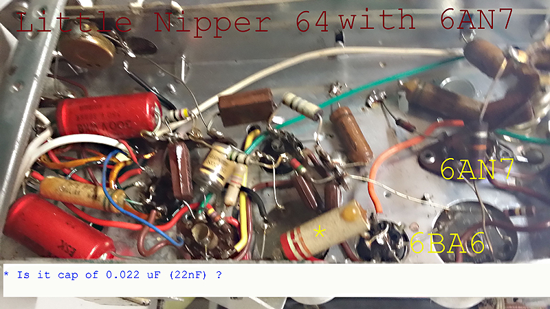
There is a ( I think) Capacitor that I cant seem to find on the Schematics of either the 64 Circuit or the 65
I have found lots of threads here in regard to the 64 with the 6AN7 Valve although some useful information...nothing that help me directly
So I just need to confirm ...that it is a cap and that its Value is 0.022 μF (22nF)
****************************************************
EDIT
ITS A RESISTOR
see Marc's comments below..
(if you really need to) Thanks Marc 
***************************************************
it comes off the 2nd IF Can on what I think is B+ ? and goes to pin 6 of the 6BA6 this then is connected to pin one of the 6AN7 via an orange hookup wire....(thats if I got the pinouts right)...pin one then goes to ground Via a 0.047 μF paper wax (now gone and replace)
Cheers All and thanks again for any info you can pass on.
Edit Thank you Brad
I should add;
I cant quite get an accurate reading off it capacitance wise and why the quire
it sort of bounces around 2nF (so maybe it is stuffed)
I am not very familiar with Cap Colour codes and maybe what I see as the third band (orange) is for Voltage
(and I can't find a cap on the schematics that matches this position)
So thought Id ask as I know someone here would know what it is in a heart beat.
|
|
|
|
|

|
Location: Wangaratta, VIC
Member since 21 February 2009
Member #: 438
Postcount: 5715
|
It is extremely unlikely that you will get a capacitance reading of that big thing red red orange.
That's a 22K resistor from B+ to the screens. If there is a decoupling cap it will be 0.1 perhaps 0.05μF, off of one of those pins to ground
Don't bother to measure the waxed paper ones, just get rid of them.
Marc
|
|
|
|
|
|
|
Location: Central Coast, NSW
Member since 18 April 2014
Member #: 1554
Postcount: 215
|
Thanks Marc
I'am an idiot ......ROFL well the Wax on it threw me and I knew caps had a colour code as well so up the garden path I wondered
Thought it didnt make sense its position and tests I hadn't chased out the circuit just recapped
but when I looked at the position I couldn't find it on the schematic
I'll check it now in a new light as resistor and look it up in the parts list and schematic
well this is really a red face moment but I guess we all have them
PS the only reason I was measuring it Marc was to try to confirm its capacitance a lot of the time I've found they read near value but thats not there problem as you have well pointed out to me in the past...(leakage)
Thanks again Marc for pointing out the error on my part...no wonder nothing made sense I just didnt twig to it being a resistor!
|
|
|
|
|
|
|
Location: Wangaratta, VIC
Member since 21 February 2009
Member #: 438
Postcount: 5715
|
One of the traps with capacitors, is that they may give a correct reading whilst leaking like a sieve. An Ohm meter is for the most part, useless in measuring that leakage.
I have an insulation tester of a type Altronics still market. This is useful for non polarised caps within its output range. At this point in time all waxed paper capacitors are considered "past their use by date". Rarely, when randomly checked, do I see a good one.
At the caps rated voltage 200Meg or less, for a screen decoupler is a fail. 50Meg or less, for a plate to grid coupling cap is also a fail.
That resistor is likely two watt (did not check current draw) In the Nippers there were some where two 22K in parallel had been replaced by a single 1 Watt 10K. Accounts dept? Unfortunately the current draw is over 10mA & 10mA is the red line for 10K, so they cook.
Marc
|
|
|
|
|
|
|
Location: Central Coast, NSW
Member since 18 April 2014
Member #: 1554
Postcount: 215
|
|
|
|
|
|
|
|
Location: Central Coast, NSW
Member since 18 April 2014
Member #: 1554
Postcount: 215
|
Just an update
seems the intermittent is still there
(but that above speaker issue did need to be fixed)
Anyway
|
|
|
|
|
|
|
Location: Wangaratta, VIC
Member since 21 February 2009
Member #: 438
Postcount: 5715
|
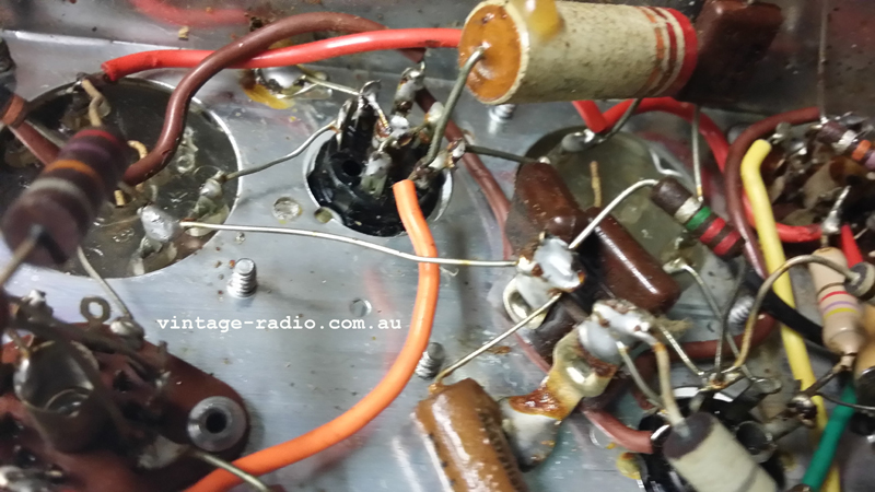
Flashovers can occur from debris & solder blobs being to big. The latter, in the case of what's on my bench, as an example; The lazy sod did not clear the old rubbish from the terminals. Not all he did wrong but I will fix that as I rewire it.
If the secondary of the OP transformer or the speaker VC go open, it is quite common for the transformer to "ring". If it does it will generate EHT and that will often flash to the nearest pins often plate to screen.
Marc
|
|
|
|
|
|
|
Location: Central Coast, NSW
Member since 18 April 2014
Member #: 1554
Postcount: 215
|
Thanks Marc yeah it was a suspicion only not 100% sure it was the case but the audio was low and distorted and after I found that it actually wasn't solder just (hoped) it might be the fault...
But seems not, as its still dropping out audio wise intermittently...so more work to do ..and as you know the chase may be merry but the answer is always simple "once you find it .."
It does work well went its working just drops out every now and again and I cant seem to induce the fault
it is a little ruff and a bit of a clean around the pins solder joints wouldn't be a bad idea anyway so I will Marc
BTW Marc what ceramic sockets would you recommend
(or are they all new stuff from china anyway..meaning all the same manufacture)
I've got a plum 11 20 that a pins broken from the Wafer, I could try gluing it but think better to just replace the wafer socket and I know you recommended ceramics for a 6M5 valves and rectifiers
(the plums using a 6AN7(A) *6B8G 6M5 & 6X5GT *marked on front as 6G8G suspect it to be 11 20 K model from PDF)
I guess I'll get a few from Evatco if they are any good (or no choice) as I got to order some caps etc soon
Thanks again
|
|
|
|
|
|
|
Location: Wangaratta, VIC
Member since 21 February 2009
Member #: 438
Postcount: 5715
|
Have not had issues with EVATCO & sockets. Replacing a damaged socket with new is often the best option & on valves like Rectifiers & OP ceramic tends to be better with prolonged heat exposure, that's why you see them on globes in "Bain Maries" ovens etc.
Monitor the B+ Voltage that may be a clue and check that you do not have a grid resistor going open, or a dud coupling cap sending it positive. Silver Mica caps can do that sort of thing too.
Marc
I note with the "Cub" radio of the week, that it's missing valve should have nine pins...... so does a 6AN7.
|
|
|
|
|

|
Administrator
Location: Naremburn, NSW
Member since 15 November 2005
Member #: 1
Postcount: 7624
|
I note with the "Cub" radio of the week, that it's missing valve should have nine pins...... so does a 6AN7.
Yes it is. Don't do a search on '6AN7' though, I've been reminded of this so many times. I should update this and will - along with some new ROTW pictures also ready to upload.
‾‾‾‾‾‾‾‾‾‾‾‾‾‾‾‾‾‾‾‾‾‾‾‾‾‾‾‾‾‾‾‾‾‾‾‾‾‾‾‾‾‾‾‾‾‾‾‾‾‾‾‾‾‾‾‾‾‾‾‾‾‾‾‾‾‾‾‾
A valve a day keeps the transistor away...
|
|
|
|
|
|
|
Location: Wangaratta, VIC
Member since 21 February 2009
Member #: 438
Postcount: 5715
|
No need search, seen one of them & their circuit, I am one of those who noted it's absence.
Marc
|
|
|
|
|
|
|
Location: Central Coast, NSW
Member since 18 April 2014
Member #: 1554
Postcount: 215
|
Thanks Marc and yes when I get back to the nipper I will do as advised...I am a little sus of those 10K's in parallel and since they cop just about the total current draw probably best to replace them anyway (for long term reliability if nothing else)
there's a few that thought very close to spec I am not happy with and I do remember you mentioning in another post that in these nippers Mica caps can be fair game... to failure...along with any resistors from that period... they all (any of them) could well be history too ...its a mixed bag in there with the resistors...looks like they use whatever was to hand or buyable at the time
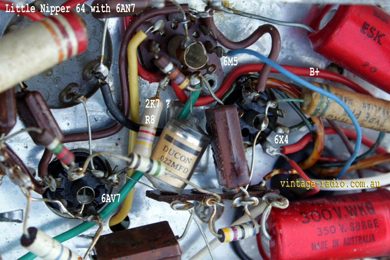
Actually coming to think of it there's one cap I didnt replace (besides the mica's) hanging of the 6M5 the Polystyrene Capacitor, you can see it in the first photo..Ducon 0.22 μF 400V CORRECTION: ITS NOT ITS A 0.022 μF ( 22nF ) C16 on 64 Schematic
left error for clarity of this thread
(I thought Polystyrene's were fairly reliable but maybe I got that wrong)
On the plum yeah I am pretty sure its the K version and just chased out the 6M5 and 6AN7 Circuit (so far) for reference
No worries on the sockets I'll grab them from Evatco then, just thought someone might make a better wheel so as to speak and why I asked... I figured you'd know
You are right of course and more to my thinking ..just cut to the chase and replace it is the best way to go..and as you say they handle heat much better
Really none of these radios were ment to last the distance they have I suppose so its a testament to them that we can still breath life into to them for really not a big outlay for the most part
(The case came up really well and it was intact too... wonder of wonders )
Thanks Marc
|
|
|
|
|
|
|
Location: Wangaratta, VIC
Member since 21 February 2009
Member #: 438
Postcount: 5715
|
One must consider that in many cases caps were tested on a percentile basis and even new you can get failures. The small clear plastic Styrene (Styroseal) types (for one) are vulnerable to heat (one in first photo) and I have seen a few of the caramel types of the 70's, cracking. That's the reason why I have the means of leakage and value testing.
The ability to quality assure & control modern polymers, has lead to stronger dielectric strength and more reliable films. So stuff like Polyester, is a lot more stable (PVC is not). One problem I have noted is the decomposition of the plastics used in formers, the Wood & Ceramic ones are proving to be superior ones in lasting. Some of the Wooden pulleys were not made of the right type, but if you give them a thin coat of high strength Araldite that solves that.
0.22mfd is a big cap; I have not looked at the circuit of that, but the only place I would (as with the Astor KJ on the bench) expect to find a cap like that, near a 6M5 is in a tone circuit or on B+ as an RF decoupler, which is where the Astor has its only 0.22μF (now that I have put it in... missing?). On the Plate of the 6M5 0.0022mfd is more likely; you will not get much out put if a 0.22mfd is there.
The 0.22μF is to decouple RF from the B+. It can get in internally and via the mains. It should be there as the Electrolytics are poor decouplers of RF. Some HMV sets I have serviced actually have an NP cap across an electrolytic on the screens for just that reason.
The thing to remember is that the circuit that the set left the factory with did work. So if you reset it to that, it should work. HMV tended to make good sets.
The set on the bench here has been done by a hacker serviceman apart from the rubber wire from transformer to antenna having to be replaced. I have diodes in the PSU and no compensation, a 6K8 not a 6J8, Seven resistors replaced so far, one cap missing, filters up rated & an 80 will be destroyed by them. A couple of wax papers were to hard to get out so the tap on the volume was disconnected & caps left, wrong values like a 0.068mfd not a 0.02mfd coupling to the 6V6.
These are the things to lookout for before even contemplating firing up the set. It was bought as it had a nice case. The guy said it didn't go..... fancy that.... The goose that tried to fix it probably "flipped it" rather than face up to the reality that as a radio serviceman, he was a complete failure & has left repairers like me a lot of extra work, that would not have had to be done had they left it alone.
Marc
|
|
|
|
|
|
|
Location: Central Coast, NSW
Member since 18 April 2014
Member #: 1554
Postcount: 215
|
Hi Marc,
First off... I must apologise for one BigTypo, I type the wrong Values for the Cap it is 0.022 μF ( 22nF )
(I even checked and still missed it...brain fade moment.  ) )
I made a comment above based on a forum reply here, that the 64 fitted with the 6NA7 is the same (or closely follows) the 65 Circuit this is incorrect upon further examination (I suspected it wasn't anyway and should have shut my mouth till I was sure).
Id say hybrid with differences is more what it is, kind of the evolution of the two.
For peoples Reference..
Here a link to the HMV page at Kevin Chants Website
http://www.kevinchant.com/hmv2.html.
Worth bookmaking his site
Main page
http://www.kevinchant.com/.
The 6M5 Circuit seems to follow more closely the 64 schematic with the 6BE6 this has 0.022 μF as C16
from pin 7 6AV6 to a 47K feeding the 6M5 pin 2.
I did do a quick capacitance check of the 0.022 μF it seemed ok but erred more on the side that its probably a more reliable component and since heat is a real enemy to them decided to leave it alone.
As you say Marc, they once worked and if you just replace whats faulty with the newer equivalent part they should work again.
Yes I know that lesson and have had it reinforced here
"resist all temptation to plug it in and see if it works".
Go through it first and replace what you find (or know) is faulty along with checks which I have done, still that dont mean more faults wont appear as seems to be the case here...sadly but well the nature of things I guess.
--
Anyway the power supply in this unit does follow the 65 Schematic except for the 150 R resistor
this seems to be done with a Voltage divider of a 47 R & 68 R and from the junction feeds a 1 Meg resistor that goes pin 5 (if I read my pins right) of the 6AV6.
This set if I understand "back bias" correctly is of that configuration....unlike the 64 version with the 6BE6 (thought I've yet to fully chase out the circuit... )
Edit: as far as the psu concerned I just checked and it appears to be the same barring the two resistors and what it powers via that...)
---
Anyway I dont know if a schematic of this unit exists, but you need to work between the 64 fitted with the 6BE6 converter and the 65 schematic with 6AN7 noting the differences to make sense of this one schematically I think.
Of course those that know radio valve circuitry well will be able to more quickly make sense of it all but for Noobs like me a good reference schematic helps...
I should properly chase this one out for future reference and post it up for others.
Yes I do agree there are a lot of cowboys out there that would do any radio a big favour by not being inside them and I hope I dont fall into that category.... thought I am not the best at reworking Valve tech...more so my reluctance to possibly cause damage to things like coils and IF's which are somewhat irreplaceable as a new part thought sure things can be gotten around ...still the less you disturb things the less chance of damage....so I try to do things on the only whats necessary or preemptive nature that I am aware may well result in failures.
I think sadly very true, a lot just Flip them and let them become someone elses problem.
( I once worked at a place were a bunch of PCB's had done the tech merry go round and then landed with me.. I chased the fault done to the original PCB as the problem...seems when made the etching had been a bit over done and tracks had been dissolve away...these things would never have worked...sadly it wasn't caught in the manufacture stage before the boards had been loaded component wise and soldered).
As much as I like authenticity I really cant understand why people try to save capacitors that really are bin material...I've seen this a few times lately.
I was lucky * NOT with the plum its pretty much untouched apart from what seems to be an addition at some point of an Electrolytic cap...it fits the period (50/60) but I've yet to chase out the power supply and see why its actually there...I know these had a few variations in PSU build.. cap values and the use of a resistor, tapped resistor and a Choke in some..not to mention speakers.
* its seems mostly untouched but someone has definitely reworked the PSU... adding an extra 8 uf...still the rest seems orginal
I'll do a separate thread on that one when I get to it....
Thanks again Marc and again sorry for the boo boo on my part...with the cap value.
|
|
|
|
|
|
|
Location: Central Coast, NSW
Member since 18 April 2014
Member #: 1554
Postcount: 215
|
EDIT THANKS Brad for pointing out my error in stating the value of the resistor...and I am stuffed if I know how that happened
-----
Hi All OK
Just a quick Question
If you look at the 64 Circuit, R8 is a 270K
The same resistor on the 65 Circuit marked R13 is 220K
(that makes sense from the little I know of valves)
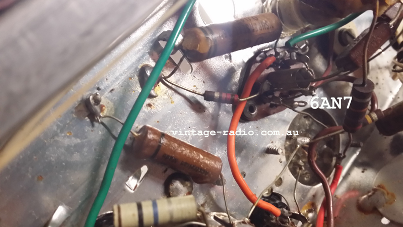
Now on this nipper its (2K7) "Correction 4K7" which is connected to B+ and plate (anode) of the 6AV7 (pin 7)
the Cap C16 (on 64 circuit) 0.022 μF comes off pin 7
Would a plate resistor be that low in value ???
It is marked as such and measures that value.."this is true thought 4K7 is the value I read"
I thought this hadn't been touched but looking at the resistor its a later made one Id say and the only one of that type in the radio...just wondering if someone may have replaced that resistor and stuffed up with the value...? (apart from me reading it...)
(I doubt its the problem I might be looking for, this circuit seems to be done differently so I dont have a true reference to go by but this may well be something that should be fixed ..so why the question I asked above).
Edit: On closer inspection with a loop it does look like a replacement.
IGNORE 2K7 on the Photo, its a "4K7" resistor and measures as such..(my mistake there)
Thank you all All.
PS was going to post last night but was getting 500 internal errors on this site...wasn't sure what was happening as up here atm we have NBN being rolled out in both flavours I think so the nets been real screwy.
|
|
|
|
|
|
You need to be a member to post comments on this forum.
|