Welcome to Australia's only Vintage Radio and Television discussion forums. You are not logged in. Please log in below, apply for an account or retrieve your password.
Australian Vintage Radio Forums
  Home  ·  About Us  ·  Discussion Forums  ·  Glossary  ·  Outside Links  ·  Policies  ·  Services Directory  ·  Safety Warnings  ·  Tutorials

Tech Talk

Forum home - Go back to Tech talk

 AWA 617T alignment
« Back · 1 · Next »
 Return to top of page · Post #: 1 · Written at 1:37:18 PM on 23 August 2014.
Scraps's Gravatar
 Location: Blue Mountains, NSW
 Member since 10 March 2013
 Member #: 1312
 Postcount: 401

I wonder if someone might have a copy of an article by Rodney Champness about aligning an AWA 719C console in the April 2002 issue (#163) of Silicon Chip they could send me? The online article refers to a series of diagrams at the end of the article that shows an alignment table as well as a couple of diagrams showing physical locations, these are not contained in the online version.

I am (foolishly?) attempting to align an AWA 617T seven bander which is the same as the 719C. I do have the circuit for this and have completed recapping and replacing out of spec resistors as well as the IF alignment. The circuit has absolutely no alignment information but I've collected a lot of information from other models thanks to the article by Rodney. The alignment data for the 611T is very similar but the component numbers are different as well as some other minor details. I also have the alignment data for a 276 which shows physical locations but again the circuit is slightly different with different component numbers. I think I have the component numbers figured out but with 19 different adjustments I'm not so sure I've matched these up to the physical locations. If someone happened to have the full AWA service info with alignment data that would be just as good.

Cheers,

Warren


 Return to top of page · Post #: 2 · Written at 1:32:36 AM on 4 September 2014.
DJ Oz's avatar
 Location: Central Coast, NSW
 Member since 18 April 2014
 Member #: 1554
 Postcount: 215

I probably have that issue but who knows where...my mags are all over the place ...
I'll have a look tomorrow night Scraps.

But hopefully someone will come to the rescue sooner then I

Gee see the can of worms you have with this one...nice set thought Smile


 Return to top of page · Post #: 3 · Written at 11:37:43 AM on 4 September 2014.
Scraps's Gravatar
 Location: Blue Mountains, NSW
 Member since 10 March 2013
 Member #: 1312
 Postcount: 401

I managed to cobble together an alignment table using all the gathered info and tracing the wiring through the eight level band change switch to all the trimmers and padders. Although there is not a lot of difference circuit wise between the various AWA 7 banders, the spread of the bands varies considerebly. For instance the 276 broadcast band covers 550-1500kHz with 1500-1600kHz covered on the 75-200 metre band. The 611 broadcast band covers 540-1500kHz and the 617T covers 540-1600kHz. The shortwave bands differ as well.

Restoring and aligning this radio has been a mammoth task, much more than just a recap and replacing out of spec resistors. It had four resistors that measured in spec but drifted after about 15 minutes causing different and very strange problems. Each time I thought I'd fixed it another problem would be revealed. I seriously considered replacing all resistors but I wanted to keep some originality. , It also had two leaky micas, one noisy mica, a 6J8G that became noisy after about 10 minutes, a 6U7J that had an intermittent cathode short, a really strange gravity dependent intermittent fading which turned out to be a factory fitted short between B+ and the plate of the IF amplifier. This took days to find as it only occurred when the chassis was installed in the cabinet, I'm quite adept at removing and installing these large chassis now!

The alignment had also been tweaked by a previous 'expert'. It was all worth it though, what a magnificent radio. The Sydney stations boom in from 100 km away with sound quality rivaling FM. It easily picks up 2WG in Wagga during the day which is over 400 km's away.

The guy I bought it off told me it was a good performer until it stopped working a few years ago. I seriously doubt it worked properly from the factory.

If anyone ever attempts one of these I'd be happy to pass on the alignment table.


 Return to top of page · Post #: 4 · Written at 12:09:49 PM on 4 September 2014.
Marcc's avatar
 Location: Wangaratta, VIC
 Member since 21 February 2009
 Member #: 438
 Postcount: 5239

I believe in an earlier article May 2001 there was mention of a chart AORSM Vol 6 1947 that could be of assistance. There is a link via google to the 2002 article but the link has been highjacked by some other mob. Clearly one I won't be dealing with.

That reads similar to setting some Multi-band Midwest's from the mid thirties. One was immediately confronted with a four gang tuner. and a mass of trimmers & padders and to add interest an amplified AGC.

It has also an interesting trap (for the inexperienced) tuning order. Starting with the factory set master trimmer at 60MHz. You start this one at the highest frequency as there is a trimmer on a gang to balance it. . Once you have set it, touch it & you throw every band off.

Why such a hassle? Its a separately excited Colpitts oscillator and they use a pair of oscillator gangs.


 Return to top of page · Post #: 5 · Written at 7:00:37 PM on 4 September 2014.
DJ Oz's avatar
 Location: Central Coast, NSW
 Member since 18 April 2014
 Member #: 1554
 Postcount: 215

OMG what a nightmare Scraps

Sorry couldn't find that issue but seems you got it sorted...go buy a lottery ticket mate after that some good lucks got to come in

I'll look again at some point cause you got me curios (I just have an odd feeling in one article what should have been there wasn't)

I am glad thought it was well worth the trouble ....that just makes the enjoyment so much better when things work well

Cheers Smile

PS there a 617 on ebay at the moment
http://www.ebay.com.au/itm/AWA-RADIOLA-617TY....

$400 is the ask for it


 Return to top of page · Post #: 6 · Written at 7:33:05 PM on 4 September 2014.
Scraps's Gravatar
 Location: Blue Mountains, NSW
 Member since 10 March 2013
 Member #: 1312
 Postcount: 401

Thanks DJ Oz, I'd appreciate that if you find it.

There's a photo coming of the B+ short, it's obvious in the photo what the problem was but not easy to find. All the wiring and components around here were untouched so it's happened during assembly at the factory.

AWA 617T Radio Chassis


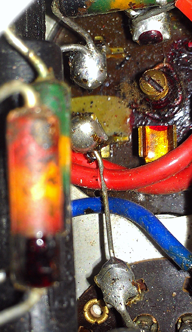
 Return to top of page · Post #: 7 · Written at 8:59:43 PM on 4 September 2014.
Marcc's avatar
 Location: Wangaratta, VIC
 Member since 21 February 2009
 Member #: 438
 Postcount: 5239

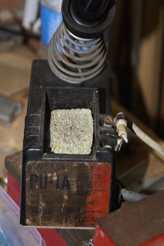
I am suspicious of that wire, it looks too new to be original & its plastic. A lot of sets of that era had either cloth rubber, or various grades of self destructing rubber. The only thing that had commonly had plastic wire in red & blue was the speaker transformer. Rubber does not melt like plastic & Silicon rubber is often found in wire that is exposed to some low heat & needs to flex. I have it on the veteran 1968 soldering iron, as it survives being clipped by the tip.

Watch those resistors, that which looks like a 50K, 500K were no better, tend to have a high attrition rate, especially when on the grid of OP valves like 6V6.

It is a common problem, where some genius monkeys with any adjustment that moves, after the set fails. I had an Airzone 504 chassis recently that was initially very deaf: IFT's were miles out. Got 2CH no problems 500Km+

Whilst it is recommended by HMV and others, that you re-align after changing RF parts, as that can throw them off, in particular IFT's, it really is mandatory.

I normally use a frequency counter & CRO to align. Beware: Do not calibrate the sig gen with the tone (modulation) on, as that can throw them off & too much signal can cut AGC / AVC in (when fitted) and that will stop the IFT's calibrating properly. I always calibrate them first.


Marc


 Return to top of page · Post #: 8 · Written at 9:36:26 PM on 4 September 2014.
GTC's avatar
 GTC
 Location: Sydney, NSW
 Member since 28 January 2011
 Member #: 823
 Postcount: 6678

I have it on the veteran 1968 soldering iron, as it survives being clipped by the tip.

Would that perchance be a Weller, such as mine (from 1969)?

http://i169.photobucket.com/albums/u218/gtc_photos/Stuff/DSC02150.jpg.


 Return to top of page · Post #: 9 · Written at 9:37:42 PM on 4 September 2014.
Scraps's Gravatar
 Location: Blue Mountains, NSW
 Member since 10 March 2013
 Member #: 1312
 Postcount: 401

It's a very late production 617TW, I've read they were still selling 617's in 1952 which isn't bad considering the design was from the late 1930's. The wiring certainly looks original, the red is B+ and the blue is the screens.

The resistor at the top is indeed a 50k (R22) on the line from the diode to the volume pot and measured at 56k but was one that was subsequently replaced. The other two resistors are on the phono input (R19 & R20) and measured within 10% at 54k and spot on 20k.

One unusual feature on this one that I haven't seen on others is a voltage select switch under a screw on panel at the rear with about five ranges between 110 volts and 250 volts, obviously with an eye to the export market.


 Return to top of page · Post #: 10 · Written at 11:53:19 PM on 4 September 2014.
Marcc's avatar
 Location: Wangaratta, VIC
 Member since 21 February 2009
 Member #: 438
 Postcount: 5239

There were a wild range of voltages until we got state grids & power stations like Spencer St & others around the place were phased out. At one point Broken Hill was running 110V.

I call 10% out the limit & replace past that.

Some early designs were spectacular. I did some repairs on an AWA special (1930's) loosely based on an R301. But had a 6A6 on chassis as the OP. R301is back biased and the PP amp was a plug in add on. Not this one.

Despite delayed AGC it still had a Local DX switch? 1st IF is a Bandpass filter on both but they changed the frequency on this one. It had been monkeyed with, so I had to sort out a few errors. The bandpass filter had been messed with / up. I had a working oscillator & nothing got past the 1st IF (bandpass).

It was obvious no expense had been spared with this one. No hum at full volume, Sound you had to hear to believe. Sensitivity unbelievable. On 66 ft of wire a station 60 miles away had to have the sensitivity switch on medium during the day.

My iron is a "Lotering" made by Matson Automotive Industries. Plug in elements of which I have 3.


« Back · 1 · Next »
 You need to be a member to post comments on this forum.

Sign In

Username:
Password:
 Keep me logged in.
Do not tick box on a computer with public access.