
Tech Talk
Forum home - Go back to Tech talk
|
Eclipse Regen 3 Valve - anyone seen one before?
|
|
|
« Back ·
1 ·
Next »
|
|
|
Return to top of page · Post #: 1 · Written at 5:45:03 PM on 15 August 2014.
|
|

|
Location: Perth, WA
Member since 19 November 2008 Member #: 381 Postcount: 240 |
|
I have acquired a 3 valve regenerative radio. 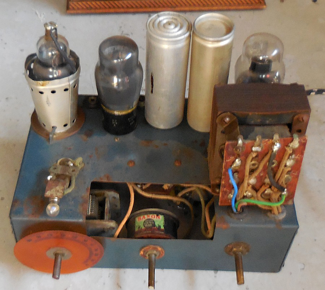 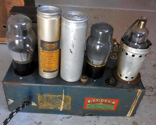 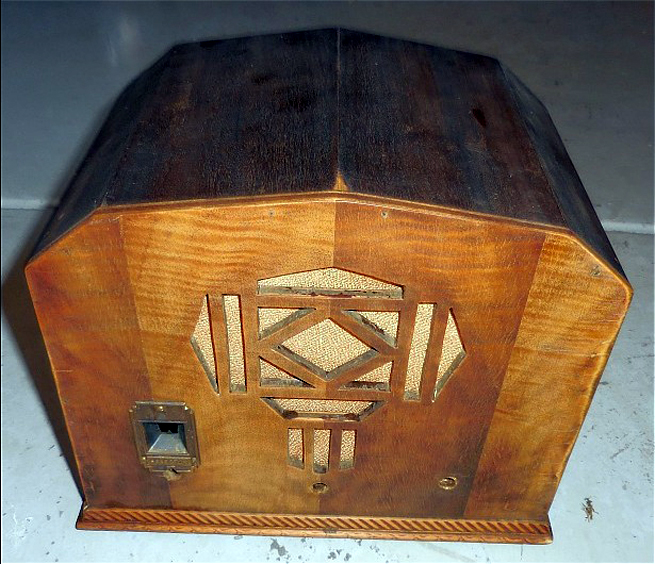 |
|
|
Return to top of page · Post #: 2 · Written at 10:52:27 PM on 15 August 2014.
|
|

|
Location: Wangaratta, VIC
Member since 21 February 2009 Member #: 438 Postcount: 5715 |
|
Cabinet is interesting: If its not to be a shelf queen? One should be able to get a speaker & use resistors to replace the field (Which appears to be missing). |
|
|
Return to top of page · Post #: 3 · Written at 9:31:44 AM on 16 August 2014.
|
|
|
|
Location: Perth, WA
Member since 19 November 2008 Member #: 381 Postcount: 240 |
|
It has a Amplion ED speaker, underneath is not too bad. It will make an interesting project to get it going. |
|
|
Return to top of page · Post #: 4 · Written at 10:14:28 AM on 16 August 2014.
|
|

|
Location: Melbourne, VIC
Member since 20 September 2011 Member #: 1009 Postcount: 1263 |
|
I found three 3 valve Eclipse circuits from 1933 & 1934. These circuits use a 57 & 2A5 which are 2.5 volt versions of a 6C6 & 42 respectively. Is it possible that the power transformer may have been changed at some stage to suit 6.3 volt valves? Or is it all original? There might be something here you can work with. |
|
|
Return to top of page · Post #: 5 · Written at 10:26:08 AM on 16 August 2014.
|
|
|
|
Location: Perth, WA
Member since 19 November 2008 Member #: 381 Postcount: 240 |
|
Transformer looks original. It might have taps. The oldest Eclipse circuit for 3 valves I have is a battery set in the 1938 Radio Trade Annual. But it is a superhet. I would appreciate a copy of the circuilts you have? Email is on my profile. |
|
|
Return to top of page · Post #: 6 · Written at 11:05:29 AM on 16 August 2014.
|
|
|
|
Location: Wangaratta, VIC
Member since 21 February 2009 Member #: 438 Postcount: 5715 |
|
It is not inconceivable that a transformer heater change was one change & the valves the other, with no actual change to the circuit, as like several valves in that era., the only change, was either the base, or the filament voltage and the rest was the same as it always was. |
|
|
Return to top of page · Post #: 7 · Written at 11:55:55 AM on 16 August 2014.
|
|
|
|
Location: Hobart, TAS
Member since 6 May 2013 Member #: 1337 Postcount: 73 |
|
I have an 1931 Astor Aladdin 3 valve regenerative console receiver. It has a similar looking chassis to yours. It was in quite good original condition when I obtained it as luckily it had been stored in a dry place for many years. After replacing some perished wiring with new cloth covered hook up wire and installing new capacitors underneath the chassis and a new three core power cable it worked quite well. I left the original capacitors in place but disconnected for appearance. The resistors were all original wire wound and still within the original1/4 ohm range and did not require replacing. The power and audio transformers, RF coil, valves and dynamic speaker were all in good condition with no shorts or open circuits.The receiver is working well. It is not as sensitive as a superheterodyne receiver, but with a good aerial and an earthed chassis via a new three core power cord it easily receives all my local stations with good volume. |
|
|
Return to top of page · Post #: 8 · Written at 1:06:40 PM on 16 August 2014.
|
|
|
|
Location: Perth, WA
Member since 19 November 2008 Member #: 381 Postcount: 240 |
|
Hi Sam, |
|
|
Return to top of page · Post #: 9 · Written at 1:48:55 PM on 16 August 2014.
|
|
|
|
Location: Perth, WA
Member since 19 November 2008 Member #: 381 Postcount: 240 |
|
Just fired it up. only a 6.3V filament winding. Makes a noise like it is trying to receive. Transformer looks original. All high voltage wiring exposed on top of the chassis! I'll have to put a cover over it. |
|
|
Return to top of page · Post #: 10 · Written at 9:50:26 PM on 16 August 2014.
|
|
|
|
Location: Hobart, TAS
Member since 6 May 2013 Member #: 1337 Postcount: 73 |
|
Hi Gary, the chassis on the Astor has a similar layout, but has Phillips valves with 4 volt filaments, an E452T detector/RF amplifier, E443N output, and a 80 rectifier. The tuning gang is on top of the chassis on the Astor with the dynamic speaker mounted underneath as it is a console model. |
|
|
Return to top of page · Post #: 11 · Written at 10:10:20 PM on 16 August 2014.
|
|
|
|
Location: Wangaratta, VIC
Member since 21 February 2009 Member #: 438 Postcount: 5715 |
|
I hope you are not running that with old electrolytics & wax paper caps in it? It may struggle to not cook something. However you now know that the valves are likely working enough to get it going properly. |
|
|
Return to top of page · Post #: 12 · Written at 10:35:34 PM on 16 August 2014.
|
|
|
|
Location: Hobart, TAS
Member since 6 May 2013 Member #: 1337 Postcount: 73 |
|
Hi Marc, I disconnected the original electrolytic capacitors and installed new 600 volt rated capacitors under the chassis in the Astor Aladdin and powered it up very slowly with a variac after checking the transformer for shorts, replacing rotten wiring and checking the resistors are within spec while keeping an eye on the HT voltage. As it is a TRF regenerative receiver there is no intermediate frequency to calibrate, instead I have to adjust the amount of feedback the detector/RF valve receives so it doesn't oscillate. |
|
|
Return to top of page · Post #: 13 · Written at 9:41:26 AM on 17 August 2014.
|
|
|
|
Location: Perth, WA
Member since 19 November 2008 Member #: 381 Postcount: 240 |
|
I remove the inside of the wet electrolytics, clean out the inside. Then epoxy a 22μF 450v radial electrolytic inside. Epoxy the positive lug into the end with a wire protruding for the negative. It’s a lot of work but I have seen wet electros leaking in the past and damaging the cabinet and chassis. 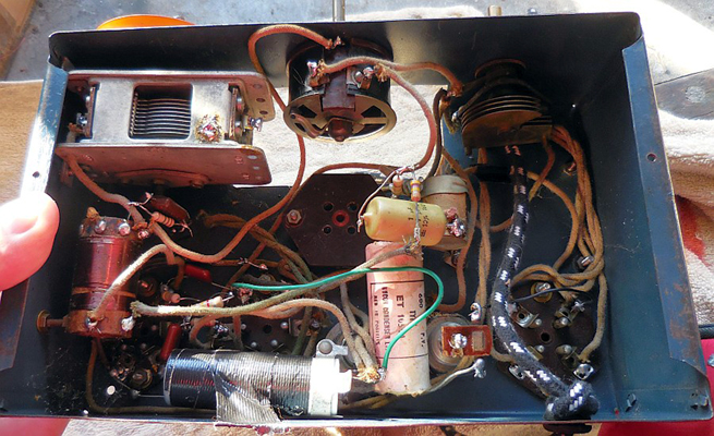 |
|
|
Return to top of page · Post #: 14 · Written at 12:22:33 PM on 17 August 2014.
|
|
|
|
Location: Wangaratta, VIC
Member since 21 February 2009 Member #: 438 Postcount: 5715 |
|
My issue with this is that if it has wax paper caps, these can seriously impinge on bias as they are all likely leaking to an unpredictable level. Plate to grid coupling caps leaking can send the bias on the grid positive and that will affect performance to a significant level. |
|
|
Return to top of page · Post #: 15 · Written at 10:15:25 AM on 29 August 2014.
|
|
|
|
Location: Perth, WA
Member since 19 November 2008 Member #: 381 Postcount: 240 |
|
Here it is restored; 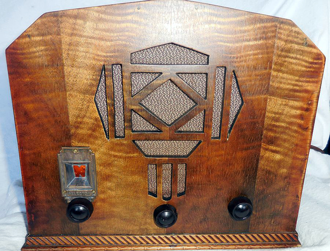 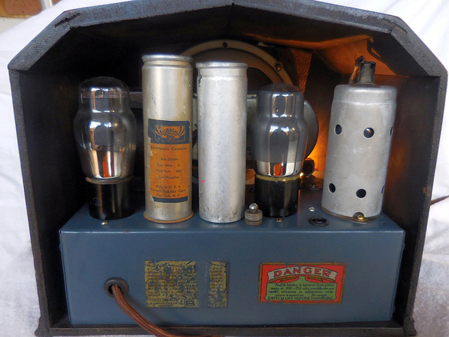 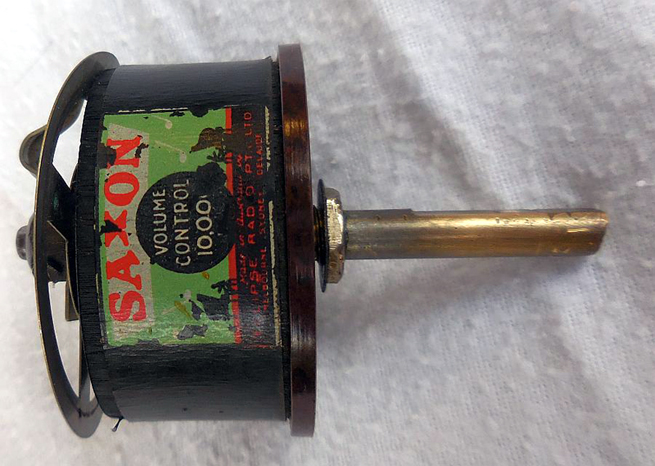 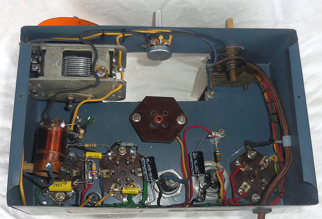 The schematic was drawn from the HRSA article, April 93. Unfortunately the nice bakelite pot was beyond repair. The radio is shown with the wrong knobs. I am trying to locate a correct set. Eclipse Circuit Diagram |
|
|
« Back ·
1 ·
Next »
|
|
|
You need to be a member to post comments on this forum.
|
|
 250V B+; Grid -4.3 (with respect to cathode..... measure across cathode resistor with high impedance meter). SG 100V. (AWA)
Sign In
Vintage Radio and Television is proudly brought to you by an era where things were built with pride and made to last.
DISCLAIMER: Valve radios and televisions contain voltages that can deliver lethal shocks. You should not attempt to work on a valve radio or other electrical appliances unless you know exactly what you are doing and have gained some experience with electronics and working around high voltages. The owner, administrators and staff of Vintage Radio & Television will accept no liability for any damage, injury or loss of life that comes as a result of your use or mis-use of information on this website. Please read our Safety Warning before using this website.
WARNING: Under no circumstances should you ever apply power to a vintage radio, television or other electrical appliance you have acquired without first having it checked and serviced by an experienced person. Also, at no time should any appliance be connected to an electricity supply if the power cord is damaged. If in doubt, do not apply power.
Shintara - Keepin' It Real · VileSilencer - Maintain The Rage