
Tech Talk
Forum home - Go back to Tech talk
|
Pye Stereo 22 Major R17-A - docs or info wanted
|
|
|
Return to top of page · Post #: 1 · Written at 2:45:18 PM on 19 May 2014.
|
|
|
|
Location: Canberra, ACT
Member since 23 August 2012 Member #: 1208 Postcount: 587 |
|
Picked up a wreck from the tip and can't resist the challenge of trying to get it going, and perhaps even looking OK. 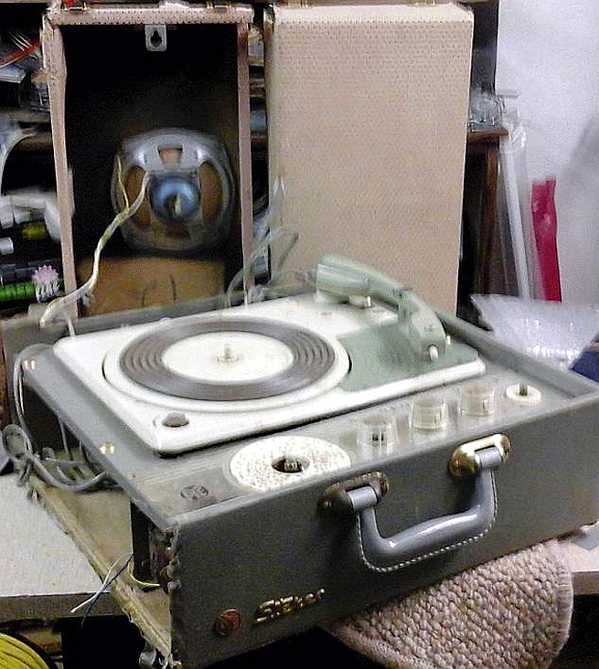 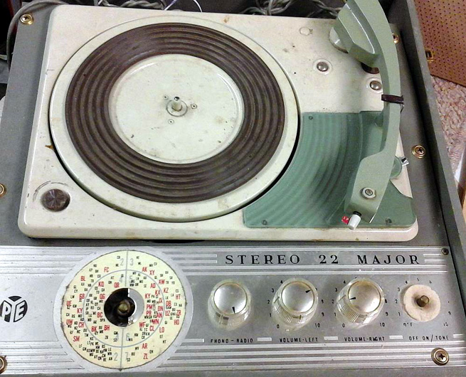 Valve lineup is: 2 x 6BM8 (stereo output from gram) 1 x 6N8 1 x 6AN7 1 x rectifier - appears burned out and labels illegible, possibly 6X4 or 6V4? Not plugging in for a while yet - will follow safe procedures to check from power forward first. Sending in a "before" picture so I can feel good about "after", however far I get with this. Note the horrible lettering style on anodised aluminium face plate, cheesy plastic knobs. Relates to my earlier posts about Australian radio designers. Was this style ever considered chic? A previous owner painted the speakers pink, and the insides of it smell like talcum powder! That young female owner probably in 70s by now. Maven |
|
|
Return to top of page · Post #: 2 · Written at 4:13:33 PM on 19 May 2014.
|
|

|
Location: Sydney, NSW
Member since 28 January 2011 Member #: 823 Postcount: 6882 |
|
You're in luck. Unhide your email address and I'll send you what I have. |
|
|
Return to top of page · Post #: 3 · Written at 5:12:49 PM on 19 May 2014.
|
|
|
|
Location: Canberra, ACT
Member since 23 August 2012 Member #: 1208 Postcount: 587 |
|
Done. What a great resource this Forum offers! |
|
|
Return to top of page · Post #: 4 · Written at 5:19:12 PM on 19 May 2014.
|
|
|
|
Location: Sydney, NSW
Member since 28 January 2011 Member #: 823 Postcount: 6882 |
|
Okay, sent. |
|
|
Return to top of page · Post #: 5 · Written at 5:56:16 PM on 19 May 2014.
|
|
|
|
Location: Canberra, ACT
Member since 23 August 2012 Member #: 1208 Postcount: 587 |
|
Received with thanks  |
|
|
Return to top of page · Post #: 6 · Written at 11:51:40 PM on 28 May 2014.
|
|

|
Location: Daylesford, VIC
Member since 13 January 2011 Member #: 809 Postcount: 326 |
|
Thanks for posting these pictures. Obviously Pye's Australian gramophones were quite different from the British models I remember. I doubt that the Stereo 22 was ever considered pretty. I don't think it's ugly, it just looks business-like, the sort of machine that a school might buy. |
|
|
Return to top of page · Post #: 7 · Written at 3:03:06 PM on 29 May 2014.
|
|

|
Location: Wangaratta, VIC
Member since 21 February 2009 Member #: 438 Postcount: 5595 |
|
Most PYE stuff here was built by Astor. Do note with PYE and Astor (main offenders) That they had a habit of mounting a perfectly innocent looking Output transformer on an insulated mounting and then putting B+ on it. |
|
|
Return to top of page · Post #: 8 · Written at 3:58:50 PM on 29 May 2014.
|
|
|
|
Location: Canberra, ACT
Member since 23 August 2012 Member #: 1208 Postcount: 587 |
|
Yes, this stereo model has two of those OP transformers with full B+ on the primary. The other end of that coil is pin 6 (pentode plate) on a 6BM8. Secondary coil of the OP feeds back to the cathode and second grid of that pentode. Beyond my understanding. |
|
|
Return to top of page · Post #: 9 · Written at 11:02:19 PM on 29 May 2014.
|
|
|
|
Location: Wangaratta, VIC
Member since 21 February 2009 Member #: 438 Postcount: 5595 |
|
Ahhh different. They put B+ on the body of the transformer, HMV chassis 01 also used the tapped transformer with 6BM8 cant think of the amp type name at the moment but it did get a lot more noise out of them. |
|
|
Return to top of page · Post #: 10 · Written at 11:03:55 PM on 29 May 2014.
|
|
|
|
Location: Sydney, NSW
Member since 28 January 2011 Member #: 823 Postcount: 6882 |
|
They put B+ on the body of the transformer |
|
|
Return to top of page · Post #: 11 · Written at 9:55:18 PM on 30 May 2014.
|
|
|
|
Location: Ballarat, VIC
Member since 4 January 2011 Member #: 803 Postcount: 456 |
|
To stop the transformers breaking down and developing B+ shorts to chassis. They didn't have much faith in the insulation of the transformers back then for good reason! |
|
|
Return to top of page · Post #: 12 · Written at 11:06:42 PM on 30 May 2014.
|
|
|
|
Location: Sydney, NSW
Member since 28 January 2011 Member #: 823 Postcount: 6882 |
|
^ I can understand the transformer being insulated from chassis to avoid the effects of insulation breakdown, but why put B+ voltage on the transformer body -- if that's what Marc is suggesting? |
|
|
Return to top of page · Post #: 13 · Written at 9:41:54 AM on 31 May 2014.
|
|
|
|
Location: Canberra, ACT
Member since 23 August 2012 Member #: 1208 Postcount: 587 |
|
I guess that if the transformer body is floating at B+ voltage rather than at ground, there won't be any potential across the insulation between coils and body. But I haven't heard of insulation material being broken down by potential - the usual factor is heat, I would think, or chemical deterioration over time. Potential-effect would have to infer some sort of electrolytic migration of molecules into or through the insulation material. |
|
|
Return to top of page · Post #: 14 · Written at 9:14:09 PM on 31 May 2014.
|
|
|
|
Location: Wangaratta, VIC
Member since 21 February 2009 Member #: 438 Postcount: 5595 |
|
By putting B+ on the whole transformer that meant you actually only had plate to screen voltage across it. which took a lot of stress off of the insulation. |
|
|
Return to top of page · Post #: 15 · Written at 3:40:36 PM on 3 June 2014.
|
|
|
|
Location: Canberra, ACT
Member since 23 August 2012 Member #: 1208 Postcount: 587 |
|
Now I've replaced all electros and paper caps, plus a few resistors that were way off, and got an EZ81 to deliver B+. |
|
|
You need to be a member to post comments on this forum.
|
|
Sign In
Vintage Radio and Television is proudly brought to you by an era where things were built with pride and made to last.
DISCLAIMER: Valve radios and televisions contain voltages that can deliver lethal shocks. You should not attempt to work on a valve radio or other electrical appliances unless you know exactly what you are doing and have gained some experience with electronics and working around high voltages. The owner, administrators and staff of Vintage Radio & Television will accept no liability for any damage, injury or loss of life that comes as a result of your use or mis-use of information on this website. Please read our Safety Warning before using this website.
WARNING: Under no circumstances should you ever apply power to a vintage radio, television or other electrical appliance you have acquired without first having it checked and serviced by an experienced person. Also, at no time should any appliance be connected to an electricity supply if the power cord is damaged. If in doubt, do not apply power.
Shintara - Keepin' It Real · VileSilencer - Maintain The Rage