Welcome to Australia's only Vintage Radio and Television discussion forums. You are not logged in. Please log in below, apply for an account or retrieve your password.
Australian Vintage Radio Forums
  Home  ·  About Us  ·  Discussion Forums  ·  Glossary  ·  Outside Links  ·  Policies  ·  Services Directory  ·  Safety Warnings  ·  Tutorials

Tech Talk

Forum home - Go back to Tech talk

 Grid Dip Meter (or Oscillator)
« Back · 1 · Next »
 Return to top of page · Post #: 1 · Written at 3:44:49 PM on 15 March 2014.
Tinkera123's Gravatar
 Location: Melbourne, VIC
 Member since 5 October 2009
 Member #: 555
 Postcount: 465

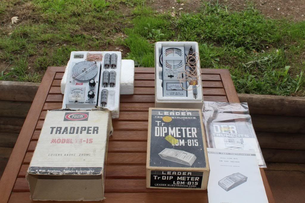
I have had a GDM for a few years but have never mastered its use. I'm sure that I have the theory sorted out. (Leader LDM - 815).

A month or so ago, a member of this Forum mentioned using a GDM ... I think it may have been Scraps. So I dug out my GDM and have been using it to test simple LC circuits. But I have a problem.

Using an old IF coil and a small capacitor in parallel, and using GDM as described in Manual, I am seeing quite a large 'dip' in meter at 18MHz when rotating meter dial from high to low. However, when rotating the meter dial from low to high, the 'dip' occurs around 28MHz. This is very repeatable.

Also, I expected the 'dip' to be smooth eg an inverted 'Bell shape', but my dip is smooth leading into the dip, but a rather sharp 'flick' out of the dip.

When I screw the slug out, both frequencies move higher, as they should.

There is no slippage between dial and variable cap.

Frequency Counter confirms that the GDM dial frequencies are reasonably accurate .... in both 'rotating' directions.

I have tried 'shorting' the tank circuit between each test.

I do not understand why I have this difference in frequency measurements.

Any suggestions???

Cheers,
Ian


‾‾‾‾‾‾‾‾‾‾‾‾‾‾‾‾‾‾‾‾‾‾‾‾‾‾‾‾‾‾‾‾‾‾‾‾‾‾‾‾‾‾‾‾‾‾‾‾‾‾‾‾‾‾‾‾‾‾‾‾‾‾‾‾‾‾‾‾
Cheers, Ian

 
 Return to top of page · Post #: 2 · Written at 4:12:29 PM on 15 March 2014.
Scraps's Gravatar
 Location: Blue Mountains, NSW
 Member since 10 March 2013
 Member #: 1312
 Postcount: 401

Sorry, it wasn't me although I've experienced something similar when playing around with IF coils and parallel capacitors with a signal generator and oscilloscope to see what frequency they would couple at. To be honest I had no idea what I was doing and even less chance of interpreting the results so I'm not really much help.

Have you continued past the first dip to see if there's a second?


 Return to top of page · Post #: 3 · Written at 5:24:42 PM on 15 March 2014.
Gandhn's Gravatar
 Location: Cameron Park, NSW
 Member since 5 November 2010
 Member #: 770
 Postcount: 387

Are the IF transformers radio types, 175kHz, 455kHz etc?
If so, any response at 18 or 28MHz is nothing to do with the IFT. If you have put a low value cap in parallel with the coil, the dip will be even lower than the correct IF.
Harold


 Return to top of page · Post #: 4 · Written at 6:17:20 PM on 15 March 2014.
Simplex's Gravatar
 Location: Bathurst, NSW
 Member since 7 August 2008
 Member #: 336
 Postcount: 391

Would depend on the frequency of the I.F coil and whether the capacitor put in parallel is the correct value.

Only thing I can think of, otherwise the coil should resonate at its normal frequency.

I have the same GDO, a Leader LDM-815 and they are a handy device.

Also a Tech Tradiper TE-15 which goes down to 440kHz, the 815 only goes to 1.5MHz which may explain why there are difficulty with I.F transformers if they are of the 175/455kHz variety.

Edit: sometimes it helps to move the GDO coil away from the tuned circuit under test to avoid over coupling.


 Return to top of page · Post #: 5 · Written at 7:26:31 AM on 17 March 2014.
Simplex's Gravatar
 Location: Bathurst, NSW
 Member since 7 August 2008
 Member #: 336
 Postcount: 391

Image Link

Here are a couple of GDO's I have used over the years and found to be useful devices.

Checking resonance of aerials, tuned circuits and whether oscillators are running are some of the operations I have used a GDO for.


 Return to top of page · Post #: 6 · Written at 2:21:53 PM on 17 March 2014.
Tinkera123's Gravatar
 Location: Melbourne, VIC
 Member since 5 October 2009
 Member #: 555
 Postcount: 465

Thanks for the responses ... I will answer them and explain what else I have done .....

"Have you continued past the first dip to see if there's a second?" ...........
Yes, but no second dip when moving dial in the same direction. That is, when frequency of GDM is increasing ..... 1 dip. When frequency decreasing ..... only 1 dip. My first thought was some type of hysterisis.

"Are the IF transformers radio types, 175kHz, 455kHz etc?".........
I probably misled you by my description as an IF coil. To be more specific, they are coils which appear to be 'harvested' from IF type cans. I don't know if they are radio or approx L. However, you inspired me to do the maths and calculate an approx L .... these coils only have 16 turns of thick copper wire (27 thou), coil length 12mm, coil dia 8mm .... my calculator says 1.0uH for air core.

Add 34.5pF capacitor in parallel and I should get resonance at 27.1MHz.

I removed the slug and re-tested, GDM dips between 22.1MHz to 30.8MHz depending on coupling, see below. I think resonance is 24.1MHz.

"sometimes it helps to move the GDO coil away from the tuned circuit under test to avoid over coupling." .......
Following SImplex's comment, I tried a variety of couplings strengths .....

Strong coupling
Freq decreasing 22.1MHz increasing 30.8MHz

Weaker coupling
Freq decreasing 23.4 and 26.1

etc

Weakest coupling ....... 24.1MHz whether increasing or decreasing frequency.

So it would seem that coupling strength is part of the answer, but I still don't know why I only see 1 dip when I rotate the dial either up or down. I expected to see boths dips irrespective of which direction I rotated the dial.

Any suggestions??

Simplex, checking resonance of aerials is where I was headed. What is a Dip meter doing on your bike?? ..... Smile

Cheers,
Ian


‾‾‾‾‾‾‾‾‾‾‾‾‾‾‾‾‾‾‾‾‾‾‾‾‾‾‾‾‾‾‾‾‾‾‾‾‾‾‾‾‾‾‾‾‾‾‾‾‾‾‾‾‾‾‾‾‾‾‾‾‾‾‾‾‾‾‾‾
Cheers, Ian

 
 Return to top of page · Post #: 7 · Written at 7:56:59 PM on 17 March 2014.
Simplex's Gravatar
 Location: Bathurst, NSW
 Member since 7 August 2008
 Member #: 336
 Postcount: 391

The GDO on the bike is actually a speedo meter. Handy things they are.
Although there are far more modern and sophisticated ones than the old Cateye depicted.

As for GDO's coupling distance will affect accuracy of the readings as your tests indicated.

As for the double dips really can't offer much of an explanation, a coil with a capacitor as a tuned circuit should only have one dip.

Unless there is some sort of 2nd harmonic.

Only thing I can think of is that whenever the GDO was used always moved it away until there was just a very slight deflection of the meter.

This seemed to give greatest accuracy.

Has been a while since have used mine for the purpose you described.


 Return to top of page · Post #: 8 · Written at 5:54:34 PM on 18 March 2014.
Tinkera123's Gravatar
 Location: Melbourne, VIC
 Member since 5 October 2009
 Member #: 555
 Postcount: 465

Got out my 1953 copy of Radio Amateur's Handbook and searched for an explanation to the above ..... and thank goodness .... found it.

In a section about Grid Dip meters it states the following "with too close coupling the oscillator frequency may be "pulled" by the circuit being checked, in which case different readings will be obtained when resonance is approached from the high side as compared with approaching form the low side."

This means .......
away from the resonance frequency, the test circuit will be inductive (if high side) or capacitive (low side) ...
with tight coupling, the inductive (or capacitive) reactances get 'coupled' into the GDM LC circuit ......
and either lower (or raise) the frequency at which the oscillator is functioning ...
thus the apparent resonance frequency is pulled away from the true resonance frequency.

This does not occur when the coupling is weak.

As others have pointed out on this Forum before .... we must understand our Test equipment before we can rely on it to take good measuremnts.


‾‾‾‾‾‾‾‾‾‾‾‾‾‾‾‾‾‾‾‾‾‾‾‾‾‾‾‾‾‾‾‾‾‾‾‾‾‾‾‾‾‾‾‾‾‾‾‾‾‾‾‾‾‾‾‾‾‾‾‾‾‾‾‾‾‾‾‾
Cheers, Ian

 
 Return to top of page · Post #: 9 · Written at 9:07:20 PM on 18 March 2014.
Simplex's Gravatar
 Location: Bathurst, NSW
 Member since 7 August 2008
 Member #: 336
 Postcount: 391

Thanks for putting that up Ian, a good explanation as to what was going on.

It would not take much overloading to cause the small oscillator in a GDO to give erratic readings.


 Return to top of page · Post #: 10 · Written at 9:16:53 PM on 18 March 2014.
Marcc's avatar
 Location: Wangaratta, VIC
 Member since 21 February 2009
 Member #: 438
 Postcount: 5252

Actually I was sort of lucky. Whilst it was in need of a refit & was as presented illegal for sale & intrinsically unsafe anyway.

I scored a Heathkit GDO GD-1b 110V at a swap meet.Fortunately this came with book & it's extra coils.

That book which I consider reference rather than reading material, should be enlightening, even for another GDO.

I have not had a chance to scan it so that I can conserve it & use a copy on the bench.


 Return to top of page · Post #: 11 · Written at 7:09:12 AM on 19 March 2014.
Simplex's Gravatar
 Location: Bathurst, NSW
 Member since 7 August 2008
 Member #: 336
 Postcount: 391

Many years ago I used a valve based GDO which was 240v supplied.

One thing about the battery transistor based versions is they can be readily used outdoors.

Can't remember how many times I've used a GDO over the years, they are a very useful device.


 Return to top of page · Post #: 12 · Written at 10:27:56 AM on 19 March 2014.
Tinkera123's Gravatar
 Location: Melbourne, VIC
 Member since 5 October 2009
 Member #: 555
 Postcount: 465

"Thanks for putting that up Ian" .....

Thanks to Simplex for pointing me in the right direction ...


‾‾‾‾‾‾‾‾‾‾‾‾‾‾‾‾‾‾‾‾‾‾‾‾‾‾‾‾‾‾‾‾‾‾‾‾‾‾‾‾‾‾‾‾‾‾‾‾‾‾‾‾‾‾‾‾‾‾‾‾‾‾‾‾‾‾‾‾
Cheers, Ian

 
« Back · 1 · Next »
 You need to be a member to post comments on this forum.

Sign In

Username:
Password:
 Keep me logged in.
Do not tick box on a computer with public access.