
Tech Talk
Forum home - Go back to Tech talk
|
Measure inductance with modern DMM
|
|
|
Return to top of page · Post #: 1 · Written at 7:55:27 PM on 14 February 2014.
|
|
|
|
Location: Somewhere, USA
Member since 22 October 2013 Member #: 1437 Postcount: 896 |
|
Hi Guys, |
|
|
Return to top of page · Post #: 2 · Written at 9:37:21 PM on 14 February 2014.
|
|
|
|
Location: Cameron Park, NSW
Member since 5 November 2010 Member #: 770 Postcount: 425 |
|
It is specified at +/- 3% and will read up to 20H, so should be fine for a regular choke. When measuring, make sure that at least one end is isolated, as the power supply capacitors will upset your reading if left in circuit. |
|
|
Return to top of page · Post #: 3 · Written at 11:10:16 PM on 14 February 2014.
|
|

|
Location: Wangaratta, VIC
Member since 21 February 2009 Member #: 438 Postcount: 5595 |
|
The critical factor is it's DC resistance as that vs current draw is what governs the correct voltage of the B+ rail. |
|
|
Return to top of page · Post #: 4 · Written at 11:52:11 PM on 14 February 2014.
|
|
|
|
Location: Somewhere, USA
Member since 22 October 2013 Member #: 1437 Postcount: 896 |
|
Thanks for the replies, so if I measure inductance and DC resistance |
|
|
Return to top of page · Post #: 5 · Written at 2:36:51 PM on 15 February 2014.
|
|
|
|
Location: Cameron Park, NSW
Member since 5 November 2010 Member #: 770 Postcount: 425 |
|
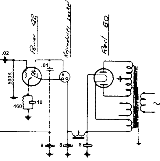
Art, I'm a little confused over your last post as you say a resistor is replacing the field coil and the radio also has a choke. Has the speaker been replaced with a permag type? If so, the field coil filtering function could be replaced with a resistor or a choke, but it is unusual to see both. |
|
|
Return to top of page · Post #: 6 · Written at 6:35:44 PM on 16 February 2014.
|
|
|
|
Location: Somewhere, USA
Member since 22 October 2013 Member #: 1437 Postcount: 896 |
|
Hi Gandhn, |
|
|
Return to top of page · Post #: 7 · Written at 10:03:02 PM on 18 February 2014.
|
|
|
|
Location: Cameron Park, NSW
Member since 5 November 2010 Member #: 770 Postcount: 425 |
|
I don't have a circuit of the Airzone 602 chassis, but I have looked at a 604 circuit on Kevin Chants site and it may be similar. Both use a 42 output valve and the 604 does indeed use a choke in the power supply and a 2000 ohm field coil speaker. |
|
|
Return to top of page · Post #: 8 · Written at 12:15:41 PM on 19 February 2014.
|
|
|
|
Location: Somewhere, USA
Member since 22 October 2013 Member #: 1437 Postcount: 896 |
|
Apparently it is.. I hear no hum, even on dead air. |
|
|
Return to top of page · Post #: 9 · Written at 11:02:28 PM on 19 February 2014.
|
|
|
|
Location: Wangaratta, VIC
Member since 21 February 2009 Member #: 438 Postcount: 5595 |
|
Model 603 lists a Magnavox 152D speaker with 2000 Ohm field and a 43 as output. It is an AC/DC model. |
|
|
Return to top of page · Post #: 10 · Written at 1:28:27 PM on 20 February 2014.
|
|
|
|
Location: Somewhere, USA
Member since 22 October 2013 Member #: 1437 Postcount: 896 |
|
I did get the 602 schematic, it has a 2000 Ohm field coil, but also an independent choke. |
|
|
Return to top of page · Post #: 11 · Written at 6:36:34 PM on 23 February 2014.
|
|
|
|
Location: Somewhere, USA
Member since 22 October 2013 Member #: 1437 Postcount: 896 |
|
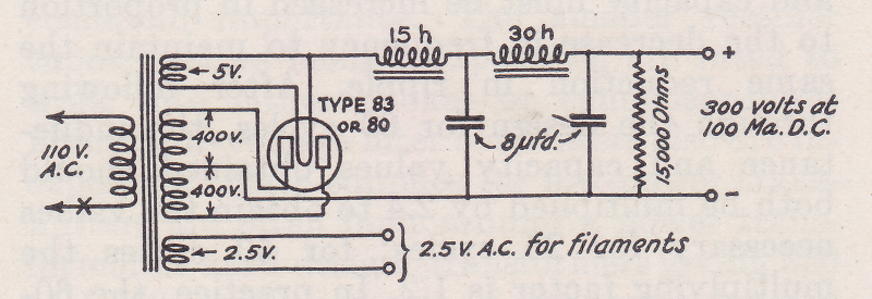
I was looking in an old ham book, and it appears the power supply |
|
|
Return to top of page · Post #: 12 · Written at 9:24:04 PM on 23 February 2014.
|
|
|
|
Location: Cameron Park, NSW
Member since 5 November 2010 Member #: 770 Postcount: 425 |
|
The circuit in your last post does not have a capacitor from the rectifier filament to ground, making it a "choke input filter". If a capacitor is connected at this point, it is a "capacitor input filter". I will have to read my old texts, but I think the difference will make a difference in voltage regulation on load. |
|
|
Return to top of page · Post #: 13 · Written at 9:00:06 AM on 24 February 2014.
|
|
|
|
Location: Wangaratta, VIC
Member since 21 February 2009 Member #: 438 Postcount: 5595 |
|
For an 80 / 5Y3 The higher the applied voltage on the plates, the lower is the input cap in value to the point that at 500V and highest current 20H choke only, no input cap. |
|
|
Return to top of page · Post #: 14 · Written at 6:08:01 PM on 24 February 2014.
|
|
|
|
Location: Somewhere, USA
Member since 22 October 2013 Member #: 1437 Postcount: 896 |
|
I stand corrected, it's not the same! |
|
|
Return to top of page · Post #: 15 · Written at 8:29:11 PM on 24 February 2014.
|
|

|
Administrator
Location: Naremburn, NSW
Member since 15 November 2005 Member #: 1 Postcount: 7548 |
|
I removed one at the weekend for the purpose of being able to access terminations for condensers I wanted to replace and it's been a while since I have done any major surgery to a radio. ‾‾‾‾‾‾‾‾‾‾‾‾‾‾‾‾‾‾‾‾‾‾‾‾‾‾‾‾‾‾‾‾‾‾‾‾‾‾‾‾‾‾‾‾‾‾‾‾‾‾‾‾‾‾‾‾‾‾‾‾‾‾‾‾‾‾‾‾ A valve a day keeps the transistor away... |
|
|
You need to be a member to post comments on this forum.
|
|
Sign In
Vintage Radio and Television is proudly brought to you by an era where things were built with pride and made to last.
DISCLAIMER: Valve radios and televisions contain voltages that can deliver lethal shocks. You should not attempt to work on a valve radio or other electrical appliances unless you know exactly what you are doing and have gained some experience with electronics and working around high voltages. The owner, administrators and staff of Vintage Radio & Television will accept no liability for any damage, injury or loss of life that comes as a result of your use or mis-use of information on this website. Please read our Safety Warning before using this website.
WARNING: Under no circumstances should you ever apply power to a vintage radio, television or other electrical appliance you have acquired without first having it checked and serviced by an experienced person. Also, at no time should any appliance be connected to an electricity supply if the power cord is damaged. If in doubt, do not apply power.
Shintara - Keepin' It Real · VileSilencer - Maintain The Rage