
Tech Talk
Forum home - Go back to Tech talk
|
Loop Antenna
|
|
|
Return to top of page · Post #: 16 · Written at 11:15:38 AM on 10 February 2014.
|
|
|
|
Location: Sydney, NSW
Member since 9 September 2013 Member #: 1407 Postcount: 12 |
|
Hi Art |
|
|
Return to top of page · Post #: 17 · Written at 11:23:58 AM on 10 February 2014.
|
|
|
|
Location: Somewhere, USA
Member since 22 October 2013 Member #: 1437 Postcount: 896 |
|
Hi Mark, |
|
|
Return to top of page · Post #: 18 · Written at 1:25:12 PM on 10 February 2014.
|
|
|
|
Location: Canberra, ACT
Member since 23 August 2012 Member #: 1208 Postcount: 587 |
|
I just had a look at the Oatley Kit instructions in a pdf available online. |
|
|
Return to top of page · Post #: 19 · Written at 5:23:40 PM on 10 February 2014.
|
|
|
|
Location: Somewhere, USA
Member since 22 October 2013 Member #: 1437 Postcount: 896 |
|
Can't answer your question of course, but there goes mine, |
|
|
Return to top of page · Post #: 20 · Written at 8:50:03 PM on 10 February 2014.
|
|
|
|
Location: NSW
Member since 10 June 2010 Member #: 681 Postcount: 1353 |
|
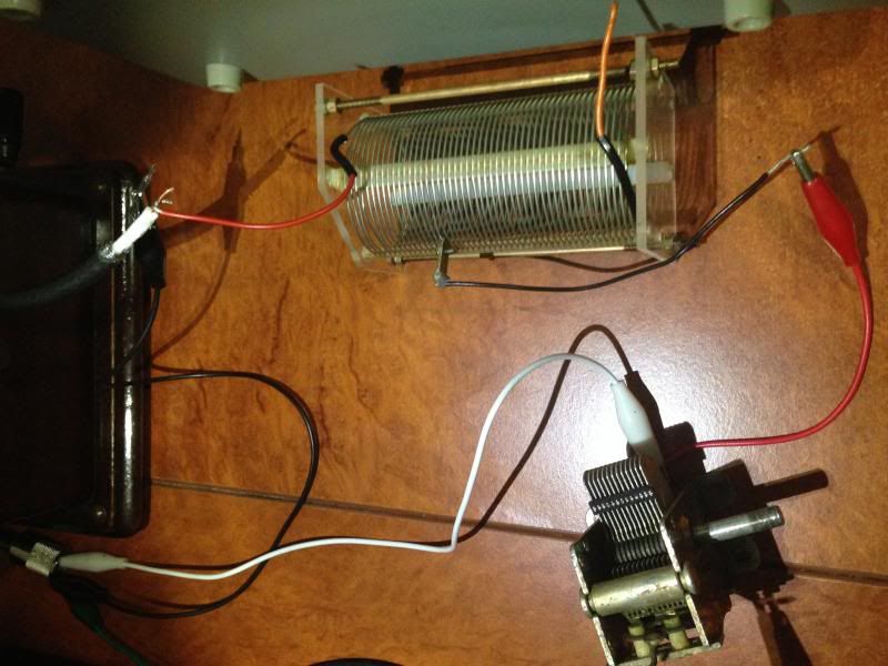
Another Oatley design I have built, the Miracle Antenna, about 20 years ago (a varicap tuned design that connected the control to the loop through coax) recommended about 6mm spacing between turns to minimise capacitance between turns. Don't know if this was a requirement of the workings of the control or to optimise Q ie sharpness of tune/selectivity, or both. |
|
|
Return to top of page · Post #: 21 · Written at 11:33:19 PM on 10 February 2014.
|
|
|
|
Location: Somewhere, USA
Member since 22 October 2013 Member #: 1437 Postcount: 896 |
|
Thinking about it, there would be nothing stopping me from twisting cloth wire together, |
|
|
Return to top of page · Post #: 22 · Written at 4:29:20 PM on 13 February 2014.
|
|
|
|
Location: Canberra, ACT
Member since 23 August 2012 Member #: 1208 Postcount: 587 |
|
Well I used flat 6-core phone cable (ie. not twisted pairs) which is the standard internal phone extension cable. I was advised not to use Cat5 data cable because the pairs are twisted. |
|
|
Return to top of page · Post #: 23 · Written at 4:45:04 PM on 15 February 2014.
|
|
|
|
Location: Sydney, NSW
Member since 9 September 2013 Member #: 1407 Postcount: 12 |
|
Hello |
|
|
Return to top of page · Post #: 24 · Written at 10:48:18 AM on 16 February 2014.
|
|
|
|
Location: Melbourne, VIC
Member since 5 October 2009 Member #: 555 Postcount: 468 |
|
Hi Maven, ‾‾‾‾‾‾‾‾‾‾‾‾‾‾‾‾‾‾‾‾‾‾‾‾‾‾‾‾‾‾‾‾‾‾‾‾‾‾‾‾‾‾‾‾‾‾‾‾‾‾‾‾‾‾‾‾‾‾‾‾‾‾‾‾‾‾‾‾ Cheers, Ian |
|
|
Return to top of page · Post #: 25 · Written at 7:34:28 PM on 16 February 2014.
|
|
|
|
Location: Somewhere, USA
Member since 22 October 2013 Member #: 1437 Postcount: 896 |
|
Thanks for the email |
|
|
Return to top of page · Post #: 26 · Written at 11:07:20 AM on 19 March 2014.
|
|
|
|
Location: Somewhere, USA
Member since 22 October 2013 Member #: 1437 Postcount: 896 |
|
The problem with all of these designs is they don't pass on any knowledge about an antenna by suggesting X turns of wire around a cross of X measurements. |
|
|
You need to be a member to post comments on this forum.
|
|

Sign In
Vintage Radio and Television is proudly brought to you by an era where things were built with pride and made to last.
DISCLAIMER: Valve radios and televisions contain voltages that can deliver lethal shocks. You should not attempt to work on a valve radio or other electrical appliances unless you know exactly what you are doing and have gained some experience with electronics and working around high voltages. The owner, administrators and staff of Vintage Radio & Television will accept no liability for any damage, injury or loss of life that comes as a result of your use or mis-use of information on this website. Please read our Safety Warning before using this website.
WARNING: Under no circumstances should you ever apply power to a vintage radio, television or other electrical appliance you have acquired without first having it checked and serviced by an experienced person. Also, at no time should any appliance be connected to an electricity supply if the power cord is damaged. If in doubt, do not apply power.
Shintara - Keepin' It Real · VileSilencer - Maintain The Rage