Welcome to Australia's only Vintage Radio and Television discussion forums. You are not logged in. Please log in below, apply for an account or retrieve your password.
Australian Vintage Radio Forums
  Home  ·  About Us  ·  Discussion Forums  ·  Glossary  ·  Outside Links  ·  Policies  ·  Services Directory  ·  Safety Warnings  ·  Tutorials

Tech Talk

Forum home - Go back to Tech talk
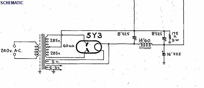
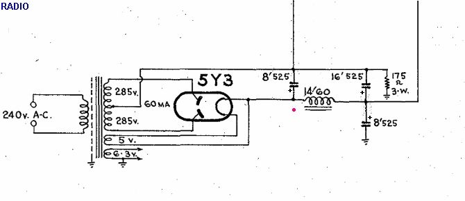
 Schematic vs Radio
« Back · 1 · Next »
 Return to top of page · Post #: 1 · Written at 2:06:33 PM on 9 November 2013.
Art's Gravatar
 Art
 Location: Somewhere, USA
 Member since 22 October 2013
 Member #: 1437
 Postcount: 896

Hi Guys,
When the schematic for my radio is re-arranged,
there is only one little difference between the schematic and the original radio.

Would it be possible to set my mind at ease?

It's down to the time to choose one or the other when soldering, and powering up the radio.

Image Link

Image Link


 Return to top of page · Post #: 2 · Written at 10:04:11 AM on 10 November 2013.
STC830's Gravatar
 Location: NSW
 Member since 10 June 2010
 Member #: 681
 Postcount: 1256

Would go for option 1 (ie ~~47jpg) because the usual arrangement is to have an 8μF cap on the valve side of a choke and a 16μF on the other.

It looks as though the175ohm resistor is there to hold the negative end of this 8μF cap above ground and the lead going off that negative end is presumably used as a bias or screen voltage somewhere. The second 8μF cap is probably there to keep ripple off that voltage.

Given that the tolerance for electro caps is large, the radio should work either way.

If the arrangement should be the other option it might show up as a hum in the speaker output. Could then patch in another 8μF cap in parallel to the existing one shown nearest the 175ohm resistor in option 1 to see if that reduces the ripple, then change to option 2 if necessary.

Good luck


 Return to top of page · Post #: 3 · Written at 10:29:09 AM on 10 November 2013.
Art's Gravatar
 Art
 Location: Somewhere, USA
 Member since 22 October 2013
 Member #: 1437
 Postcount: 896

Thanks Smile

It's the second picture that has 8μF on one side and 16μF on the other.
That is the one I went with, I figured if the radio didn't work
to begin with, it couldn't have left the factory.

Having never seen a valve radio, I don't know how bright
the glow should appear when powered up.
They (or some) did glow at the top, but it looked quite dim
in good daylight, and the room was lit.

No sound though Sad
I found my output transformer primary is also open circuit,
so have to try to find one of them on the cheap side.


 Return to top of page · Post #: 4 · Written at 10:48:55 AM on 10 November 2013.
STC830's Gravatar
 Location: NSW
 Member since 10 June 2010
 Member #: 681
 Postcount: 1256

In the ~~47.jpg picture the 16μF is connected directly to ground, so would be most effective as a filter to the right hand output line which presumably goes to do most of the HT work. So that is why I chose the first option.


 Return to top of page · Post #: 5 · Written at 11:07:50 AM on 10 November 2013.
STC830's Gravatar
 Location: NSW
 Member since 10 June 2010
 Member #: 681
 Postcount: 1256

Re brightness of the valves.

The brightest would probably be the 5Y3 since it is directly heated, so that the actual cathode heater element is visible, and powered by a higher current than the others.

The others would be indirectly heated with the heater element inside a tubular cathode. This arrangement means that the element is not electrically connected to the cathode, and minimises hum from the AC heater current. Of these valves the output valve would probably be the brightest, but this can depend on whether the mechanical construction shields the cathode assembly from sight.

Output trannies sometimes come up on ebay at reasonable prices.


 Return to top of page · Post #: 6 · Written at 12:35:36 PM on 10 November 2013.
Art's Gravatar
 Art
 Location: Somewhere, USA
 Member since 22 October 2013
 Member #: 1437
 Postcount: 896

That glow is just a matter of the 6.3 Volt heater current right?
except for the 5Y3 that uses the 5 Volt supply.
It doesn't matter what else is going on in the radio?

Since I have a new transformer with matching spec of the old one,
it's odd that they glow faint.
even the 5Y3 I would call faint, and again,
it is my understanding it shouldn't matter what's going on with the radio.

I'm reluctant to turn it on again without the output transformer.
At least this time, nothing got hot or blew up!

With regard to the output Xformer, I have that other recent
thread for some info, except my output valve is 6V6.
Does that mean I don't need one greater than 5 Watts,
and any with 5K primary should be ok?
They are not too expensive from EVATCO.


 Return to top of page · Post #: 7 · Written at 2:30:21 PM on 10 November 2013.
STC830's Gravatar
 Location: NSW
 Member since 10 June 2010
 Member #: 681
 Postcount: 1256

The glow is the result of the heater current. I didn't mention that the silver or black getter on the inside of the envelope might obscure the glow.

The glow would be red to red-orange. The really old bright emitter valves, without the white coating seen on the cathodes of your valves, run be hotter and are yellow.

The new transformer shouldn't effect how the valves glow unless there was a short somewhere in the old one. Some transformers have 220-230V primary taps as well as the 240V tap. Even though our mains voltage is nominally 230V, I've never seen it lower than 240v and it can go up to 250V. So best to use the 240V tap for best valve life. The lower taps would make the valves a little brighter.

The output transformer rated wattage should not need to be higher than the output wattage of the output valve.

As long as the output valve is taken out the radio can be turned on. Or you could wire in a resistor, with the same resistance as 6V6 output impedance and appropriate wattage, in place of the output transformer and leave the output valve in. You would then be able to check the voltages around the circuit and find any issues while the output transformer comes.

Valve characteristics can be found online, and voltage ranges for various electrodes are given. These can be used for troubleshooting if your schematic doesn't show expected voltages. In the old days these voltages were for a 1000ohm per volt meter, so will be higher for a modern digital or analogue meter especially in the low current signal areas of the circuit, eg mixer and IF stages and first stage audio amplification.

I understand that a 1000ohm/volt meter can be simulated with a digital meter by wiring a resistor, equal to 1000 x the voltage range in use, across the leads - although I have never tried this.

A good guide to old radios is given in
http://www.thebakeliteradio.com/page102/page102.html


 Return to top of page · Post #: 8 · Written at 3:35:20 PM on 10 November 2013.
Art's Gravatar
 Art
 Location: Somewhere, USA
 Member since 22 October 2013
 Member #: 1437
 Postcount: 896

Hi again,
I did use the 240 Volt tap intuitively, since the manufacturer did.
Rather than wire the fly leads out to their destinations,
I mocked the tag strip with my first ever PCB, check it out:
Image Link
Image Link

So as per "the rules", theoretically, an original Xformer could be dropped in.

The output Xformer won't be so long, I sold my iPad,
and can order it tomorrow. Selling the iPad is easy to justify.

I was first looking at HiFi output transformers over $200,
thinking that was it, but down the bottom of the page,
the 5 Watt model looks more reasonable:
http://www.evatco.com.au/hamprice.htm

Also, while you're reading, my choke in the schematic is
14H / 60mA.
Hammond have a close replacement:
Model 157L, 14H 75mA.
but that would have to be ordered directly.

Is this a suitable substitute:
for a model that is actually stocked locally:
Model 158L, 15H 75mA
Or is inductance must be matched exactly?

You could potentially save me making a mistake on either of those!

For $400, I do have a choice of getting a new working radio
or maybe not because I've not actually seen the END of those eBay auctions.
It's hard to let this one go, there wouldn't be enough change left over for the stuff this one needs.


 Return to top of page · Post #: 9 · Written at 4:24:52 PM on 10 November 2013.
STC830's Gravatar
 Location: NSW
 Member since 10 June 2010
 Member #: 681
 Postcount: 1256

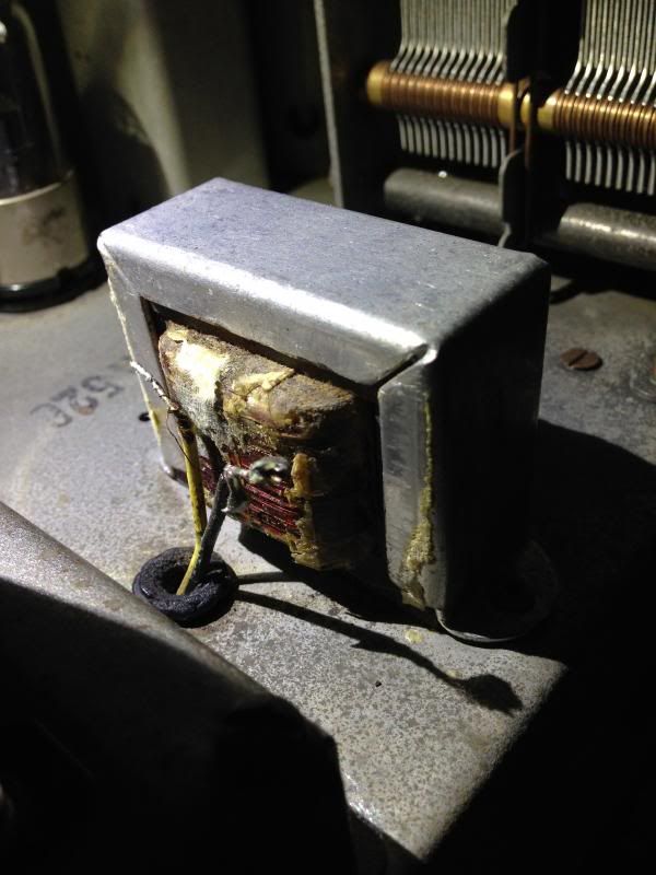
Having forked out for a new power transformer, might as well go for a new output transformer. Good for reliability especially if it is to get regular use.

If it is to go out of the workshop into regular use and you have an electrician mate it might be worthwhile getting it checked for safety, especially proper earthing (no soldered earth to chassis - needs to be a tag with nut, screw & star washer) and proper 240V cable anchoring. He could also check inter winding resistance in the mains transformer with a megga - though should be OK for a new transformer.

Re 15 Henry choke - shouldn't think that 1 henry out of 14 would make much difference. This would slightly lower the output voltage. Others might disagree - would need a calculation to be sure. 75mA is OK for 60mA replacement.

Old radios are interesting to people and you can say you restored it yourself - a good conversation point and might be worth the cost. But you might attract some love jobs!


 Return to top of page · Post #: 10 · Written at 4:51:43 PM on 10 November 2013.
Art's Gravatar
 Art
 Location: Somewhere, USA
 Member since 22 October 2013
 Member #: 1437
 Postcount: 896

Since I'm committed to getting the choke as well,
I then had confidence to lift the tape.

Funny Stuff!
It has been repaired by grabbing whatever closest winding wasn't shorted!
I wouldn't have thought of that, but not sure I'd want to either.

Image Link

and even now, that winding was open circuit Grin

I will see if I can get the 14H choke specially ordered.

Yes it is earthed standard with star washer and all.
The other mains is temporary, and uses a small high voltage insulated terminal strip for now.

I'm going to a ham radio club tomorrow night, I would likely eventually take it there.
They are all the right generation for this.


« Back · 1 · Next »
 You need to be a member to post comments on this forum.

Sign In

Username:
Password:
 Keep me logged in.
Do not tick box on a computer with public access.