
Tech Talk
Forum home - Go back to Tech talk
|
Replacement audio output transformer
|
|
|
Return to top of page · Post #: 1 · Written at 2:23:13 PM on 5 November 2013.
|
|
|
|
Location: Wahroonga, NSW
Member since 5 November 2013 Member #: 1441 Postcount: 11 |
|
Hi, this is my first post on any forum (so please be gentle!). I am repairing an HMV B61B portable and, like most of the old sets I have collected, it has an defunct output transformer (the primary is o/c). I am looking for a replacement but there are no details on the transformer. The set uses a 3V4 audio output and a 2ohm speaker. Valve data shows the load for a 3V4 is 10K with an output power of 250mW. I have searched the web but there are no direct replacement transformers - 10K/2ohm with a power output <5W. I have found a couple of possible substitutes. Hammond Mfg 125ASE multivalued 2.5 – 10K primary and 4 – 32ohm secondary (3W output); a ClassicTone 40-18052 5K/3.2ohm, or ClassicTone 40-18030 8K/4ohm both 5W types. Physical size is a bit of concern for all of them but I guess I will just have to cope with that. |
|
|
Return to top of page · Post #: 2 · Written at 3:45:04 PM on 5 November 2013.
|
|
|
|
Location: Somewhere, USA
Member since 22 October 2013 Member #: 1437 Postcount: 896 |
|
If you want it bad enough it would be happening: http://www.evatco.com.au/hamprice.htm. |
|
|
Return to top of page · Post #: 3 · Written at 3:53:30 PM on 5 November 2013.
|
|

|
Location: Sydney, NSW
Member since 28 January 2011 Member #: 823 Postcount: 6946 |
|
Output transformers reflect the secondary impedance into the primary according to the the turns ratio. So, if a transformer is 10Kohm:8ohm, putting a 4 ohm load on the secondary will present a 5Kohm load to the output valve. |
|
|
Return to top of page · Post #: 4 · Written at 9:45:36 PM on 5 November 2013.
|
|

|
Location: Tamworth, NSW
Member since 6 April 2012 Member #: 1126 Postcount: 472 |
|
I'll have a dig tomorrow. I have a few dead portable that use 3V4's. Might be something usefull in there. |
|
|
Return to top of page · Post #: 5 · Written at 9:45:04 PM on 6 November 2013.
|
|
|
|
Location: Wahroonga, NSW
Member since 5 November 2013 Member #: 1441 Postcount: 11 |
|
Thanks guiys for your comments. Great stuff, particularly GTC for your explanation. |
|
|
Return to top of page · Post #: 6 · Written at 11:04:32 AM on 7 November 2013.
|
|
|
|
Location: Tamworth, NSW
Member since 6 April 2012 Member #: 1126 Postcount: 472 |
|
I had a look last night. The only one ive found so far is out of philips 168, and it is o/c. |
|
|
Return to top of page · Post #: 7 · Written at 2:17:56 PM on 7 November 2013.
|
|
|
|
Location: Cameron Park, NSW
Member since 5 November 2010 Member #: 770 Postcount: 426 |
|
Hi Fredr |
|
|
Return to top of page · Post #: 8 · Written at 5:51:09 PM on 7 November 2013.
|
|
|
|
Location: NSW
Member since 10 June 2010 Member #: 681 Postcount: 1406 |
|
"The crook one I have shouldnt be too hard to rewind." |
|
|
Return to top of page · Post #: 9 · Written at 10:11:17 AM on 8 November 2013.
|
|
|
|
Location: Blue Mountains, NSW
Member since 10 March 2013 Member #: 1312 Postcount: 401 |
|
"The crook one I have shouldn't be too hard to rewind" |
|
|
Return to top of page · Post #: 10 · Written at 1:04:24 PM on 10 November 2013.
|
|
|
|
Location: Wahroonga, NSW
Member since 5 November 2013 Member #: 1441 Postcount: 11 |
|
Thanks guys. Much appreciated. Gandhn I've emailed you. |
|
|
Return to top of page · Post #: 11 · Written at 2:38:57 PM on 10 November 2013.
|
|
|
|
Location: Somewhere, USA
Member since 22 October 2013 Member #: 1437 Postcount: 896 |
|
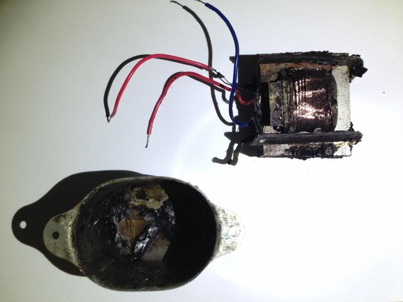
Some of it is hard and brittle and chips away like glass, |
|
|
Return to top of page · Post #: 12 · Written at 3:51:06 PM on 10 November 2013.
|
|
|
|
Location: NSW
Member since 10 June 2010 Member #: 681 Postcount: 1406 |
|
"I'd like to try it but not too sure about my skills" |
|
|
Return to top of page · Post #: 13 · Written at 4:03:03 PM on 10 November 2013.
|
|
|
|
Location: Somewhere, USA
Member since 22 October 2013 Member #: 1437 Postcount: 896 |
|
I didn't try melting it. Maybe that would work, |
|
|
Return to top of page · Post #: 14 · Written at 4:47:21 PM on 10 November 2013.
|
|
|
|
Location: NSW
Member since 10 June 2010 Member #: 681 Postcount: 1406 |
|
Could try a small piece of it and see if it melts. |
|
|
Return to top of page · Post #: 15 · Written at 5:04:17 PM on 10 November 2013.
|
|
|
|
Location: Somewhere, USA
Member since 22 October 2013 Member #: 1437 Postcount: 896 |
|
If I get an open one, I was thinking of just using the case |
|
|
You need to be a member to post comments on this forum.
|
|
 Hooking up a 8K/4 ohm transformer to a 2 ohm speaker the transformer will see a 2 ohm impedance i.e. the secondary can be considered 2 ohm. This will mean the primary impedance will be 4K (secondary is ½ the rated value means the primary will be ½ the rated value). Going back to the 3V4 with its 10K load and your comment that the 6V6 (and I guess by inference the 3V4) will handle half its rated load, using a 8K/4 ohm transformer – 2ohm speaker means the valve will see only a 4K load. Not enough I think.
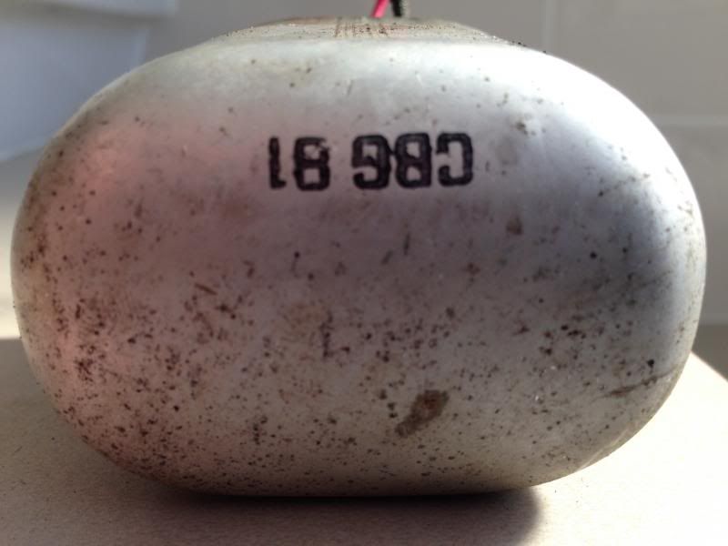
Sign In
Vintage Radio and Television is proudly brought to you by an era where things were built with pride and made to last.
DISCLAIMER: Valve radios and televisions contain voltages that can deliver lethal shocks. You should not attempt to work on a valve radio or other electrical appliances unless you know exactly what you are doing and have gained some experience with electronics and working around high voltages. The owner, administrators and staff of Vintage Radio & Television will accept no liability for any damage, injury or loss of life that comes as a result of your use or mis-use of information on this website. Please read our Safety Warning before using this website.
WARNING: Under no circumstances should you ever apply power to a vintage radio, television or other electrical appliance you have acquired without first having it checked and serviced by an experienced person. Also, at no time should any appliance be connected to an electricity supply if the power cord is damaged. If in doubt, do not apply power.
Shintara - Keepin' It Real · VileSilencer - Maintain The Rage