
Tech Talk
Forum home - Go back to Tech talk
|
Local Oscillator
|
|
|
Return to top of page · Post #: 1 · Written at 2:05:43 PM on 29 October 2013.
|
|
|
|
Location: Somewhere, USA
Member since 22 October 2013 Member #: 1437 Postcount: 896 |
|
Hi Guys, |
|
|
Return to top of page · Post #: 2 · Written at 9:32:29 AM on 30 October 2013.
|
|

|
Location: Wangaratta, VIC
Member since 21 February 2009 Member #: 438 Postcount: 5703 |
|
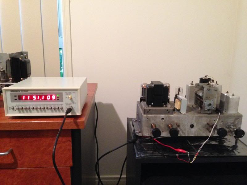
A guy in our radio club, bought a frequency counter module that he put on a device he made. |
|
|
Return to top of page · Post #: 3 · Written at 10:35:15 AM on 30 October 2013.
|
|
|
|
Location: Somewhere, USA
Member since 22 October 2013 Member #: 1437 Postcount: 896 |
|
Hi |
|
|
Return to top of page · Post #: 4 · Written at 1:14:54 PM on 30 October 2013.
|
|
|
|
Location: Oradell, US
Member since 2 April 2010 Member #: 643 Postcount: 839 |
|
A cathode follower as a buffer should work. IIRC, the waveform developed on the cathode of a 6BE6 or similar tube is about enough amplitude to feed a TTL gate, once buffered. The cathode follower should be high enough impedance to have little effect on the oscillator frequency. |
|
|
Return to top of page · Post #: 5 · Written at 5:59:04 PM on 30 October 2013.
|
|
|
|
Location: Somewhere, USA
Member since 22 October 2013 Member #: 1437 Postcount: 896 |
|
Ok, thanks. |
|
|
Return to top of page · Post #: 6 · Written at 6:03:44 PM on 30 October 2013.
|
|
|
|
Location: Somewhere, USA
Member since 22 October 2013 Member #: 1437 Postcount: 896 |
|
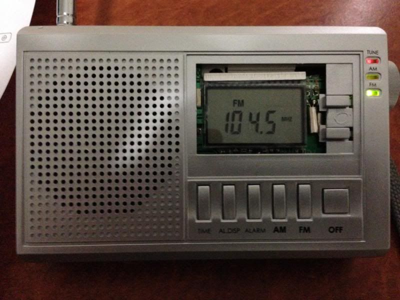
I thought it might be worth buying one of these and junking it: http://www.jaycar.com.au/productView.asp?ID=AR1741. |
|
|
Return to top of page · Post #: 7 · Written at 10:38:34 PM on 30 October 2013.
|
|
|
|
Location: Somewhere, USA
Member since 22 October 2013 Member #: 1437 Postcount: 896 |
|
The radio tuner at it's earliest stage has to be an oscillator, |
|
|
Return to top of page · Post #: 8 · Written at 2:35:19 PM on 6 November 2013.
|
|
|
|
Location: Somewhere, USA
Member since 22 October 2013 Member #: 1437 Postcount: 896 |
|
Yes, |
|
|
Return to top of page · Post #: 9 · Written at 7:58:01 PM on 6 November 2013.
|
|
|
|
Location: Wangaratta, VIC
Member since 21 February 2009 Member #: 438 Postcount: 5703 |
|
Crystal set is tuned radio frequency (TRF) there is no oscillator. |
|
|
Return to top of page · Post #: 10 · Written at 10:49:27 PM on 6 November 2013.
|
|
|
|
Location: Somewhere, USA
Member since 22 October 2013 Member #: 1437 Postcount: 896 |
|
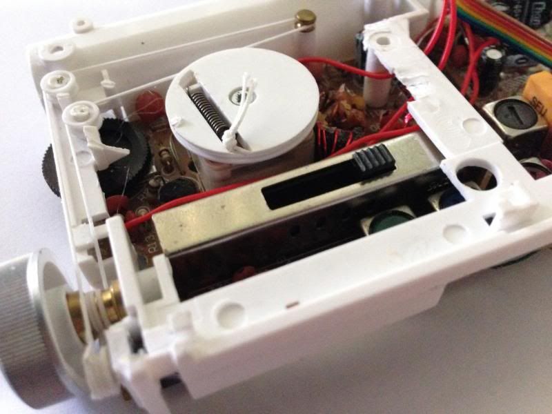
I bought this one just out of curiosity. |
|
|
Return to top of page · Post #: 11 · Written at 5:50:03 PM on 6 December 2013.
|
|
|
|
Location: Somewhere, USA
Member since 22 October 2013 Member #: 1437 Postcount: 896 |
|
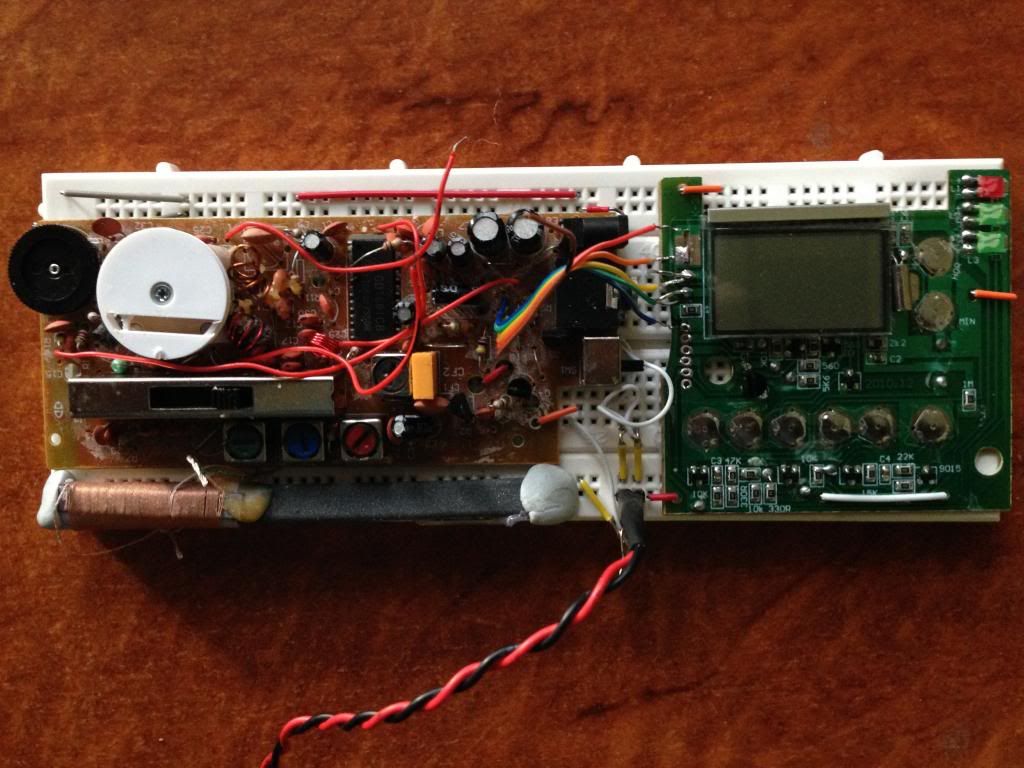
Not having much luck. |
|
|
Return to top of page · Post #: 12 · Written at 10:40:26 AM on 7 December 2013.
|
|
|
|
Location: Canberra, ACT
Member since 23 August 2012 Member #: 1208 Postcount: 587 |
|
Are you sure the LED itself is capable of responding at LO frequencies? Is the opto-couple designed for audio frequencies too low for the LO? |
|
|
Return to top of page · Post #: 13 · Written at 4:30:57 PM on 7 December 2013.
|
|
|
|
Location: Somewhere, USA
Member since 22 October 2013 Member #: 1437 Postcount: 896 |
|
Thanks for the reply Maven, |
|
|
Return to top of page · Post #: 14 · Written at 5:58:38 PM on 7 December 2013.
|
|
|
|
Location: Somewhere, USA
Member since 22 October 2013 Member #: 1437 Postcount: 896 |
|
So the transmitting side is something like this now, |
|
|
Return to top of page · Post #: 15 · Written at 5:12:39 PM on 17 December 2013.
|
|
|
|
Location: Somewhere, USA
Member since 22 October 2013 Member #: 1437 Postcount: 896 |
|
A ferrite loop antenna works when directly connected to a scope |
|
|
You need to be a member to post comments on this forum.
|
|

Sign In
Vintage Radio and Television is proudly brought to you by an era where things were built with pride and made to last.
DISCLAIMER: Valve radios and televisions contain voltages that can deliver lethal shocks. You should not attempt to work on a valve radio or other electrical appliances unless you know exactly what you are doing and have gained some experience with electronics and working around high voltages. The owner, administrators and staff of Vintage Radio & Television will accept no liability for any damage, injury or loss of life that comes as a result of your use or mis-use of information on this website. Please read our Safety Warning before using this website.
WARNING: Under no circumstances should you ever apply power to a vintage radio, television or other electrical appliance you have acquired without first having it checked and serviced by an experienced person. Also, at no time should any appliance be connected to an electricity supply if the power cord is damaged. If in doubt, do not apply power.
Shintara - Keepin' It Real · VileSilencer - Maintain The Rage