
Tech Talk
Forum home - Go back to Tech talk
|
Home-made Variac
|
|
|
Return to top of page · Post #: 1 · Written at 10:03:35 PM on 24 September 2013.
|
|

|
Location: Wauchope, NSW
Member since 1 January 2013 Member #: 1269 Postcount: 576 |
|
Hi all, |
|
|
Return to top of page · Post #: 2 · Written at 10:08:17 PM on 24 September 2013.
|
|

|
Administrator
Location: Naremburn, NSW
Member since 15 November 2005 Member #: 1 Postcount: 7618 |
|
If it was me, I'd just buy one. They are readily available from Jaycar and Ebay. ‾‾‾‾‾‾‾‾‾‾‾‾‾‾‾‾‾‾‾‾‾‾‾‾‾‾‾‾‾‾‾‾‾‾‾‾‾‾‾‾‾‾‾‾‾‾‾‾‾‾‾‾‾‾‾‾‾‾‾‾‾‾‾‾‾‾‾‾ A valve a day keeps the transistor away... |
|
|
Return to top of page · Post #: 3 · Written at 10:14:44 PM on 24 September 2013.
|
|

|
Location: Sydney, NSW
Member since 28 January 2011 Member #: 823 Postcount: 6946 |
|
Since new/second-hand variacs seem to command |
|
|
Return to top of page · Post #: 4 · Written at 10:18:37 PM on 24 September 2013.
|
|

|
Location: Wangaratta, VIC
Member since 21 February 2009 Member #: 438 Postcount: 5703 |
|
Burnt fingers likely here: Variac is an auto transformer, RCD will not save you after a rectifier on a hot chassis set. |
|
|
Return to top of page · Post #: 5 · Written at 6:57:41 PM on 25 September 2013.
|
|

|
Location: Tamworth, NSW
Member since 6 April 2012 Member #: 1126 Postcount: 472 |
|
Chris |
|
|
Return to top of page · Post #: 6 · Written at 9:20:54 PM on 25 September 2013.
|
|
|
|
Location: Maclean, NSW
Member since 30 May 2008 Member #: 291 Postcount: 341 |
|
I have one for sale, contact me via my user name. |
|
|
Return to top of page · Post #: 7 · Written at 6:55:52 PM on 26 September 2013.
|
|
|
|
Location: Wauchope, NSW
Member since 1 January 2013 Member #: 1269 Postcount: 576 |
|
Ben, I've been thinking about using a mains-rated wafer switch or a series of SPCO toggle switches. I don't think a carbon pot would have enough range for an application like this. |
|
|
Return to top of page · Post #: 8 · Written at 8:33:44 AM on 27 September 2013.
|
|
|
|
Location: Canberra, ACT
Member since 23 August 2012 Member #: 1208 Postcount: 587 |
|
If you are considering an incremental switched solution rather than a continuous arbitrary range, you might be better off looking at one or more multi-tap transformers with a rotary switch selecting the taps. I have one like that feeding a rectifier for benchtop DC supply. Assuming you are not going to need more than about 2amps, the transformers should be affordable or obtainable from salvage. |
|
|
Return to top of page · Post #: 9 · Written at 11:16:20 AM on 27 October 2013.
|
|
|
|
Location: Somewhere, USA
Member since 22 October 2013 Member #: 1437 Postcount: 896 |
|
If you load mains with a potentiometer, |
|
|
Return to top of page · Post #: 10 · Written at 9:18:29 PM on 27 October 2013.
|
|
|
|
Location: Canberra, ACT
Member since 23 August 2012 Member #: 1208 Postcount: 587 |
|
I opened up the foot-pedal speed controller from an old electric sewing machine some years ago, and it appears to be nothing but a large variable resistor across the mains supply with coils of resistance wire strung about an insulating frame. There's no switching or transformer involved, so I wonder if it is using resistance to cut voltage or just limiting current? |
|
|
Return to top of page · Post #: 11 · Written at 4:34:51 PM on 2 November 2013.
|
|
|
|
Location: Canberra, ACT
Member since 23 August 2012 Member #: 1208 Postcount: 587 |
|
Dug out my sewing-machine footpedal, and found it contains a set of 5 resistors (wire coils, as in old radiators) in series with one side of the AC 240volt mains current. The connector is a standard earthed "appliance plug" as used for toasters etc 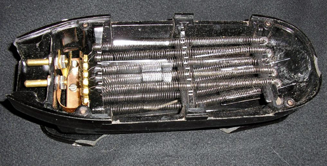 Maven |
|
|
Return to top of page · Post #: 12 · Written at 5:12:39 PM on 2 November 2013.
|
|
|
|
Location: NSW
Member since 10 June 2010 Member #: 681 Postcount: 1406 |
|
For the purpose of bringing out of service gear back into service I have a light socket screwed to a piece of particle board with the light in the active line wired to male & female GP plug and socket, neutral and earth lines going straight through. |
|
|
Return to top of page · Post #: 13 · Written at 5:33:34 PM on 2 November 2013.
|
|
|
|
Location: Somewhere, USA
Member since 22 October 2013 Member #: 1437 Postcount: 896 |
|
That's sneaky, |
|
|
Return to top of page · Post #: 14 · Written at 6:21:04 PM on 2 November 2013.
|
|
|
|
Location: NSW
Member since 10 June 2010 Member #: 681 Postcount: 1406 |
|
An idea that I haven't followed up on is connecting two or three of the auto-transformers used for pedestal fan speed control in such a way as to provide a series of voltages. |
|
|
Return to top of page · Post #: 15 · Written at 6:27:16 PM on 2 November 2013.
|
|
|
|
Location: Somewhere, USA
Member since 22 October 2013 Member #: 1437 Postcount: 896 |
|
I wonder if the caps would like PWM even if the radio does not. |
|
|
You need to be a member to post comments on this forum.
|
|
Sign In
Vintage Radio and Television is proudly brought to you by an era where things were built with pride and made to last.
DISCLAIMER: Valve radios and televisions contain voltages that can deliver lethal shocks. You should not attempt to work on a valve radio or other electrical appliances unless you know exactly what you are doing and have gained some experience with electronics and working around high voltages. The owner, administrators and staff of Vintage Radio & Television will accept no liability for any damage, injury or loss of life that comes as a result of your use or mis-use of information on this website. Please read our Safety Warning before using this website.
WARNING: Under no circumstances should you ever apply power to a vintage radio, television or other electrical appliance you have acquired without first having it checked and serviced by an experienced person. Also, at no time should any appliance be connected to an electricity supply if the power cord is damaged. If in doubt, do not apply power.
Shintara - Keepin' It Real · VileSilencer - Maintain The Rage