
Tech Talk
Forum home - Go back to Tech talk
|
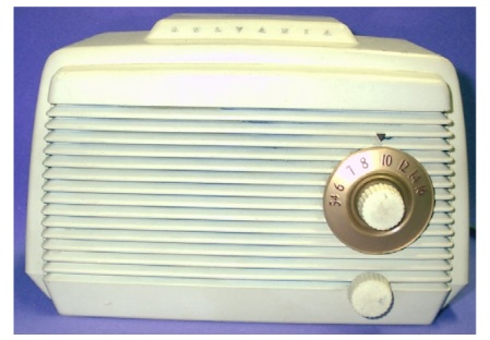
1950 Sylvania 510-H
|
|
|
« Back ·
1 ·
Next »
|
|
|
Return to top of page · Post #: 1 · Written at 11:01:16 AM on 14 September 2013.
|
|

|
Location: Wauchope, NSW
Member since 1 January 2013 Member #: 1269 Postcount: 576 |
|
Hi all, |
|
|
Return to top of page · Post #: 2 · Written at 1:49:58 PM on 14 September 2013.
|
|

|
Location: Sydney, NSW
Member since 28 January 2011 Member #: 823 Postcount: 6946 |
|
That valve line-up matches Radiomuseum's listing for a 510: |
|
|
Return to top of page · Post #: 3 · Written at 9:37:16 AM on 15 September 2013.
|
|

|
Location: Wangaratta, VIC
Member since 21 February 2009 Member #: 438 Postcount: 5703 |
|
Likely what the Americans call a AA5 circuit the layout of which is a common as dishwater. You will likely find the circuit on Nostalgia air, or there may be a "SAM's" sheet for it. |
|
|
Return to top of page · Post #: 4 · Written at 6:24:15 AM on 16 September 2013.
|
|
|
|
Location: Oradell, US
Member since 2 April 2010 Member #: 643 Postcount: 839 |
|
Your radio's schematic is likely extremely similar to this: |
|
|
Return to top of page · Post #: 5 · Written at 9:31:22 AM on 16 September 2013.
|
|
|
|
Location: Wangaratta, VIC
Member since 21 February 2009 Member #: 438 Postcount: 5703 |
|
Do note relative to my comment the .01Cap paralleled with the 0.22M resistor to chassis |
|
|
« Back ·
1 ·
Next »
|
|
|
You need to be a member to post comments on this forum.
|
|

 50Hz:
50Hz:

Sign In
Vintage Radio and Television is proudly brought to you by an era where things were built with pride and made to last.
DISCLAIMER: Valve radios and televisions contain voltages that can deliver lethal shocks. You should not attempt to work on a valve radio or other electrical appliances unless you know exactly what you are doing and have gained some experience with electronics and working around high voltages. The owner, administrators and staff of Vintage Radio & Television will accept no liability for any damage, injury or loss of life that comes as a result of your use or mis-use of information on this website. Please read our Safety Warning before using this website.
WARNING: Under no circumstances should you ever apply power to a vintage radio, television or other electrical appliance you have acquired without first having it checked and serviced by an experienced person. Also, at no time should any appliance be connected to an electricity supply if the power cord is damaged. If in doubt, do not apply power.
Shintara - Keepin' It Real · VileSilencer - Maintain The Rage