
Tech Talk
Forum home - Go back to Tech talk
|
Match line output source to pickup input
|
|
|
Return to top of page · Post #: 1 · Written at 8:56:47 PM on 17 August 2013.
|
|
|
|
Location: Canberra, ACT
Member since 23 August 2012 Member #: 1208 Postcount: 587 |
|
Now that my Radioplayer is back in full voice, I'm looking for the best way to connect standard line-level source to the old pickup terminals. First connection will be a FM tuner, and I'd like to leave it permanently connected. |
|
|
Return to top of page · Post #: 2 · Written at 9:38:59 PM on 17 August 2013.
|
|

|
Location: Wangaratta, VIC
Member since 21 February 2009 Member #: 438 Postcount: 5717 |
|
I have not looked at the circuit but, I would consider that if there is bias required on the valve via the pickup, it would have likely been a magnetic cartridge as it will pass DC. Others and capacitors will not. |
|
|
Return to top of page · Post #: 3 · Written at 8:26:31 AM on 18 August 2013.
|
|
|
|
Location: Canberra, ACT
Member since 23 August 2012 Member #: 1208 Postcount: 587 |
|
I'm a bit puzzled because I would have thought that the coil of a magnetic cartridge, with one end connected to ground, would be shorting out the bias voltage - unless it had a high resistance/impedance. |
|
|
Return to top of page · Post #: 4 · Written at 10:01:30 AM on 18 August 2013.
|
|
|
|
Location: Ballarat, VIC
Member since 4 January 2011 Member #: 803 Postcount: 456 |
|
You'll need to add a capacitor in series with the line level input to isolate the DC bias you have. Something in the order of 0.1μF (100nF) may work well but you may need to try either half or double this value if you find the tonal range is a bit off balance (ie, loss of treble or bass response). |
|
|
Return to top of page · Post #: 5 · Written at 1:12:14 PM on 19 August 2013.
|
|
|
|
Location: Canberra, ACT
Member since 23 August 2012 Member #: 1208 Postcount: 587 |
|
I tried the capacitor-in-series over a wide range of values and it didn't seem to work. With higher cap values, the radio tuner signal is completely suppressed. With lower values, more signal is maintained. At pf values, the tuner signal is not affected, but the external signal is suppressed. |
|
|
Return to top of page · Post #: 6 · Written at 8:31:34 PM on 19 August 2013.
|
|
|
|
Location: Wangaratta, VIC
Member since 21 February 2009 Member #: 438 Postcount: 5717 |
|
What model was that again? |
|
|
Return to top of page · Post #: 7 · Written at 9:33:21 PM on 19 August 2013.
|
|
|
|
Location: Ballarat, VIC
Member since 4 January 2011 Member #: 803 Postcount: 456 |
|
I too am starting to get a bit concerned about what's going on and I went back and checked the circuit for the Philips Model 123. |
|
|
Return to top of page · Post #: 8 · Written at 10:23:27 PM on 19 August 2013.
|
|
|
|
Location: Canberra, ACT
Member since 23 August 2012 Member #: 1208 Postcount: 587 |
|
Sorry if my terminology is confusing. |
|
|
Return to top of page · Post #: 9 · Written at 11:03:26 PM on 19 August 2013.
|
|
|
|
Location: Wangaratta, VIC
Member since 21 February 2009 Member #: 438 Postcount: 5717 |
|
If you have AORSM's see if any other models have that arrangement. I have a 132L. |
|
|
Return to top of page · Post #: 10 · Written at 10:43:07 AM on 20 August 2013.
|
|
|
|
Location: Canberra, ACT
Member since 23 August 2012 Member #: 1208 Postcount: 587 |
|
OK, rechecked the circuit on my radio and the Pickup connects right at the input end of the volume pot. Amended schematic shows the pickup connections. 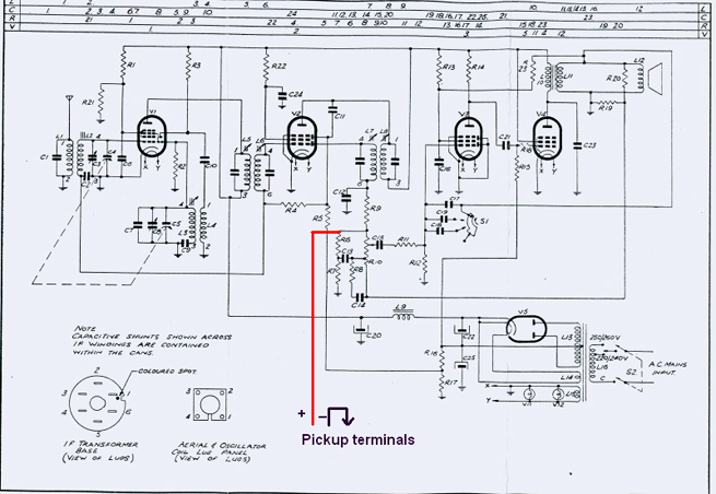 Maven |
|
|
Return to top of page · Post #: 11 · Written at 10:25:18 PM on 21 August 2013.
|
|
|
|
Location: Ballarat, VIC
Member since 4 January 2011 Member #: 803 Postcount: 456 |
|
Interesting, the connection is done correctly but the radio should also have a radio-gram switch otherwise how do you get the radio to stop while you play records? This is how it is done on the majority of radios. |
|
|
Return to top of page · Post #: 12 · Written at 10:47:42 PM on 21 August 2013.
|
|
|
|
Location: Canberra, ACT
Member since 23 August 2012 Member #: 1208 Postcount: 587 |
|
My recollection is that the radio doesn't stop - you just tune it off station and hear only the pickup signal, when that is what you want. |
|
|
Return to top of page · Post #: 13 · Written at 10:15:38 AM on 22 August 2013.
|
|
|
|
Location: Cameron Park, NSW
Member since 5 November 2010 Member #: 770 Postcount: 427 |
|
Looking at the circuit, could someone explain the connection from the speaker voice coil, via R23 to the screen of V3? |
|
|
Return to top of page · Post #: 14 · Written at 11:54:30 AM on 22 August 2013.
|
|

|
Administrator
Location: Naremburn, NSW
Member since 15 November 2005 Member #: 1 Postcount: 7630 |
|
My recollection is that the radio doesn't stop - you just tune it off station and hear only the pickup signal, when that is what you want. ‾‾‾‾‾‾‾‾‾‾‾‾‾‾‾‾‾‾‾‾‾‾‾‾‾‾‾‾‾‾‾‾‾‾‾‾‾‾‾‾‾‾‾‾‾‾‾‾‾‾‾‾‾‾‾‾‾‾‾‾‾‾‾‾‾‾‾‾ A valve a day keeps the transistor away... |
|
|
Return to top of page · Post #: 15 · Written at 9:20:23 PM on 22 August 2013.
|
|
|
|
Location: Wangaratta, VIC
Member since 21 February 2009 Member #: 438 Postcount: 5717 |
|
The output transformer has wires back, as that is part of the AF negative feedback. reverse it & the set will oscillate. |
|
|
You need to be a member to post comments on this forum.
|
|
Sign In
Vintage Radio and Television is proudly brought to you by an era where things were built with pride and made to last.
DISCLAIMER: Valve radios and televisions contain voltages that can deliver lethal shocks. You should not attempt to work on a valve radio or other electrical appliances unless you know exactly what you are doing and have gained some experience with electronics and working around high voltages. The owner, administrators and staff of Vintage Radio & Television will accept no liability for any damage, injury or loss of life that comes as a result of your use or mis-use of information on this website. Please read our Safety Warning before using this website.
WARNING: Under no circumstances should you ever apply power to a vintage radio, television or other electrical appliance you have acquired without first having it checked and serviced by an experienced person. Also, at no time should any appliance be connected to an electricity supply if the power cord is damaged. If in doubt, do not apply power.
Shintara - Keepin' It Real · VileSilencer - Maintain The Rage