
Tech Talk
Forum home - Go back to Tech talk
|
Another pot question - inverse tap?
|
|
|
« Back ·
1 ·
Next »
|
|
|
Return to top of page · Post #: 1 · Written at 3:44:49 PM on 12 August 2013.
|
|
|
|
Location: Canberra, ACT
Member since 23 August 2012 Member #: 1208 Postcount: 587 |
|
Looking at volume pot replacement, I realise that the Philips circuit uses a potentiometer type that has a 4th terminal - this terminal seems to carry the inverse of the resistance on the ouput terminals. |
|
|
Return to top of page · Post #: 2 · Written at 4:10:07 PM on 12 August 2013.
|
|
|
|
Location: NSW
Member since 10 June 2010 Member #: 681 Postcount: 1379 |
|
There is a discussion on tapped pots here: |
|
|
Return to top of page · Post #: 3 · Written at 4:41:26 PM on 12 August 2013.
|
|
|
|
Location: Canberra, ACT
Member since 23 August 2012 Member #: 1208 Postcount: 587 |
|
Thanks for that pointer. It seems the only recourse is to modify a new, standard pot to create the extra tap. |
|
|
Return to top of page · Post #: 4 · Written at 5:44:07 PM on 12 August 2013.
|
|
|
|
Location: NSW
Member since 10 June 2010 Member #: 681 Postcount: 1379 |
|
Sometimes the circuit diagram for the radio will have the value at the tap. |
|
|
Return to top of page · Post #: 5 · Written at 6:58:09 PM on 12 August 2013.
|
|

|
Location: Wangaratta, VIC
Member since 21 February 2009 Member #: 438 Postcount: 5625 |
|
Sometimes the tapping value is on the pot, or still measurable it can be 40K on a 1Meg pot, does vary. |
|
|
Return to top of page · Post #: 6 · Written at 3:46:48 PM on 13 August 2013.
|
|
|
|
Location: Canberra, ACT
Member since 23 August 2012 Member #: 1208 Postcount: 587 |
|
The radio is Radioplayer 123. The original part number for the pot is CZ.029.129, 0.5megohm tapped, but no value given for the tap itself. |
|
|
Return to top of page · Post #: 7 · Written at 10:23:55 AM on 16 August 2013.
|
|
|
|
Location: Canberra, ACT
Member since 23 August 2012 Member #: 1208 Postcount: 587 |
|
I've successfully added a 40k tap to a standard 500k potentiometer. 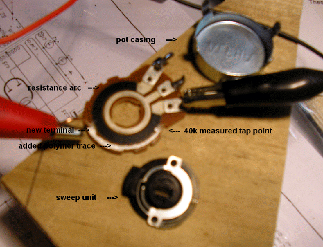 The pot was easy to disassemble. The case is only held on by 4 bent tabs. The sweep disc is held to the shaft purely by friction, as it is pushed through a slot in the plastic sweep disk mount. It could be levered off carefully without damage. The point to make a 40k tap connection is easily determined using a multimeter on the 200k resistance scale. I marked it with a pen mark on the phenolic base. A "trace pen" dispenses a trickle of liquid polymer containing metallic power. It sets to a polymer film that is fully conductive. Since the pen needs to be pumped as you draw, it is not easy to make a precise line. However, once the trace has set to a dry film, it can be trimmed back by careful scraping with a sharp point such as a scalpel or sharp knife. The best thing is that it is fully reversible - it took me several goes to get it right. The new drawn trace needs to have about 1mm clearance from the edge of the pot, to avoid any chance of shorting to the case (which is grounded). About 1mm clearance on both sides of the trace is advisable and doable. The polymer trace cannot be soldered, so you have to create a new metal terminal. Because of tight clearances within the pot case, it's best to avoid any solder joint inside the case (I tried it and it was too troublesome). My solution was to bore a 1mm hole in the base plate and push a piece of 1mm copper wire into it, pre-bent at 90degrees, then super-glued in place from the outer side. The wire inside the pot is insulated with spaghetti tube, as it needs to pass through a short slot cut in the pot case. That slot also stabilises the terminal wire. The internal electrical connection is made by painting the polymer trace fluid onto the wire. Even when fully dry, the polymer retains a small amount of resilience which should help maintain the connection if the terminal wire is bumped from outside the pot case. Here is the photo of the reassembled pot with the new tap connection poking out the back. 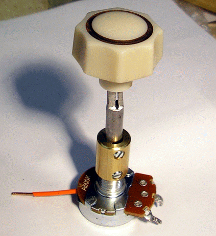 Replacing this tapped pot seems to have finally solved the volume fade problem that has been bugging me for months. However, along the way I have replaced so many components that I can't rule out several components contributing to the problem. Anyway, I think it is good news that tapped pots can be replaced even when they are no longer sold. Maven |
|
|
Return to top of page · Post #: 8 · Written at 2:15:25 PM on 16 August 2013.
|
|
|
|
Location: Blue Mountains, NSW
Member since 10 March 2013 Member #: 1312 Postcount: 401 |
|
Very interesting and inventive, I just hope I never need to do it! |
|
|
Return to top of page · Post #: 9 · Written at 2:50:55 PM on 16 August 2013.
|
|

|
Location: Sydney, NSW
Member since 28 January 2011 Member #: 823 Postcount: 6891 |
|
Yes, it's probably not something I'd undertake, but I'm looking forward to seeing the photos for future reference. |
|
|
Return to top of page · Post #: 10 · Written at 10:06:54 PM on 16 August 2013.
|
|
|
|
Location: Canberra, ACT
Member since 23 August 2012 Member #: 1208 Postcount: 587 |
|
Postscript: |
|
|
« Back ·
1 ·
Next »
|
|
|
You need to be a member to post comments on this forum.
|
|

Sign In
Vintage Radio and Television is proudly brought to you by an era where things were built with pride and made to last.
DISCLAIMER: Valve radios and televisions contain voltages that can deliver lethal shocks. You should not attempt to work on a valve radio or other electrical appliances unless you know exactly what you are doing and have gained some experience with electronics and working around high voltages. The owner, administrators and staff of Vintage Radio & Television will accept no liability for any damage, injury or loss of life that comes as a result of your use or mis-use of information on this website. Please read our Safety Warning before using this website.
WARNING: Under no circumstances should you ever apply power to a vintage radio, television or other electrical appliance you have acquired without first having it checked and serviced by an experienced person. Also, at no time should any appliance be connected to an electricity supply if the power cord is damaged. If in doubt, do not apply power.
Shintara - Keepin' It Real · VileSilencer - Maintain The Rage