
Tech Talk
Forum home - Go back to Tech talk
|
Unknown Valve Tester
|
|
|
Return to top of page · Post #: 1 · Written at 7:37:31 PM on 17 June 2013.
|
|
|
|
Location: Blue Mountains, NSW
Member since 10 March 2013 Member #: 1312 Postcount: 401 |
|
I picked up what turned out to be an unknown valve tester for next to nothing recently. I originally thought it was a Weston 777 Tubechecker but the meter is obviously a replacement and it's not a Weston Tubechecker. The only identification is D^D 965 on the transformer and the underside of the front panel. I understand it's only a very basic emission tester but that suits me fine. I've no idea of it's age but my guess is 1950's. 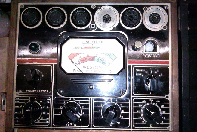 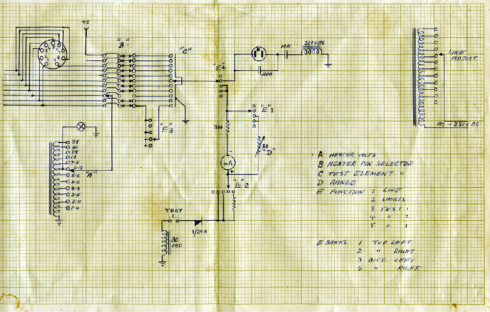 Click on image to display larger image. 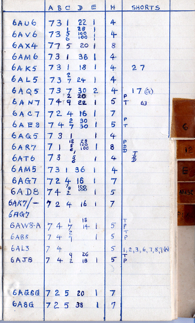 Line compensator with switch E in line position adjusts for mains variations. Switch A is the heater voltage. Switch B heater pin. The notes don't always show the lowest numbered heater pin, sometimes giving the higher numbered pin. Not sure if there's a reason for this or not. Switch C is the element to test. This took a while to figure out, it appears that for diodes the plate is selected and for triodes and pentodes the grid is selected. Why the grid for these two and not the plate? Switch D is the range, I assume for an unknown valve I'd use a known good valve and increase this to a reference point on the scale for comparison. Switch E Pos 1 - Line Adjust Pos 2 - Shorts. I think to use this setting the heater pin would be selected first and then test the elements one by one using switch C and the test button? Pos 3 - Test 1. It seems nearly all valves use this position, the only exceptions I can find are 6AQ5 and 6BQ5. Pos 4 - Test 2. The only valves in the settings using Test 2 are 6AQ5 and 6BQ5 though there's probably others not in the note book. The only difference I can find is that 6AQ5 has two connections to the grid pins 1 and 7 and 6BQ5 has nothing on pin 1. Test 2 seems to isolate pin 1? Pos 5 - Test 3. I really don't know what this is here for except possibly a heater test. Switch E appears to be shown in Pos 2 - Shorts if I'm reading the circuit right. After doing the usual safety checks and fitting an earthed 3 core flex cable, I've tested a few (expendable) valves and it seems to work okay. If anyone's familiar with this sort of tester I'd really appreciate if they could confirm what I've worked out. Cheers, Warren |
|
|
Return to top of page · Post #: 2 · Written at 7:42:27 PM on 17 June 2013.
|
|

|
Location: Wauchope, NSW
Member since 1 January 2013 Member #: 1269 Postcount: 576 |
|
All I know is that the D^D is an Australian Military marking from the 1940's-50's, as it's been found on some Australian insulators used in military applications around 1947/48. |
|
|
Return to top of page · Post #: 3 · Written at 8:16:04 PM on 17 June 2013.
|
|
|
|
Location: Blue Mountains, NSW
Member since 10 March 2013 Member #: 1312 Postcount: 401 |
|
Hi Chris, I'd wondered whether it might have been a "project piece" for a trainee technician in the Army, hence the markings. It's very well constructed with beautifully laced wiring. |
|
|
Return to top of page · Post #: 4 · Written at 8:32:22 PM on 17 June 2013.
|
|

|
Administrator
Location: Naremburn, NSW
Member since 15 November 2005 Member #: 1 Postcount: 7633 |
|
The front panel layout looks like my Paton valve tester and is about the same size and construction too. ‾‾‾‾‾‾‾‾‾‾‾‾‾‾‾‾‾‾‾‾‾‾‾‾‾‾‾‾‾‾‾‾‾‾‾‾‾‾‾‾‾‾‾‾‾‾‾‾‾‾‾‾‾‾‾‾‾‾‾‾‾‾‾‾‾‾‾‾ A valve a day keeps the transistor away... |
|
|
Return to top of page · Post #: 5 · Written at 8:42:44 PM on 17 June 2013.
|
|

|
Location: Melbourne, VIC
Member since 20 September 2011 Member #: 1009 Postcount: 1263 |
|
I reckon this valve tester might be a University Graham. It looks similar to the model TVT, except, yours doesn't have the pin selector levers. The later Paton "Palec" ET4A also had the pin selector levers. So yours may be a simpler version like the earlier Palecs and the Hickok that was discussed here a couple of months ago. |
|
|
Return to top of page · Post #: 6 · Written at 9:00:04 PM on 17 June 2013.
|
|

|
Location: Sydney, NSW
Member since 28 January 2011 Member #: 823 Postcount: 6956 |
|
I recall that D^D was a shorthand in Oz for Department of Defence. Can't recall exactly but I think it was commonly found on stuff in war surplus shops. |
|
|
Return to top of page · Post #: 7 · Written at 9:13:13 PM on 17 June 2013.
|
|
|
|
Administrator
Location: Naremburn, NSW
Member since 15 November 2005 Member #: 1 Postcount: 7633 |
|
...with the ^ being an arrow similar to the ones on old gaol and lunatic asylum uniforms. This is stamped on the bases of numerous valves I have as spares. ‾‾‾‾‾‾‾‾‾‾‾‾‾‾‾‾‾‾‾‾‾‾‾‾‾‾‾‾‾‾‾‾‾‾‾‾‾‾‾‾‾‾‾‾‾‾‾‾‾‾‾‾‾‾‾‾‾‾‾‾‾‾‾‾‾‾‾‾ A valve a day keeps the transistor away... |
|
|
Return to top of page · Post #: 8 · Written at 9:28:17 PM on 17 June 2013.
|
|
|
|
Location: Melbourne, VIC
Member since 20 September 2011 Member #: 1009 Postcount: 1263 |
|
Found it! |
|
|
Return to top of page · Post #: 9 · Written at 9:40:55 PM on 17 June 2013.
|
|
|
|
Location: Blue Mountains, NSW
Member since 10 March 2013 Member #: 1312 Postcount: 401 |
|
I've looked at 100's of photos, websites and manuals over the last week. Those two, the Paton ET3 and the University TVT are the closest I found. Switch E is always the problem, they have a different function. I think I did find a download of the TVT manual, I'll have take another look at it and see if any if the valve settings are similar. I think my switch C is a simple one in all in substitute for the levers. |
|
|
Return to top of page · Post #: 10 · Written at 9:54:21 PM on 17 June 2013.
|
|
|
|
Location: Sydney, NSW
Member since 28 January 2011 Member #: 823 Postcount: 6956 |
 |
|
|
Return to top of page · Post #: 11 · Written at 10:29:45 PM on 17 June 2013.
|
|
|
|
Location: Blue Mountains, NSW
Member since 10 March 2013 Member #: 1312 Postcount: 401 |
|
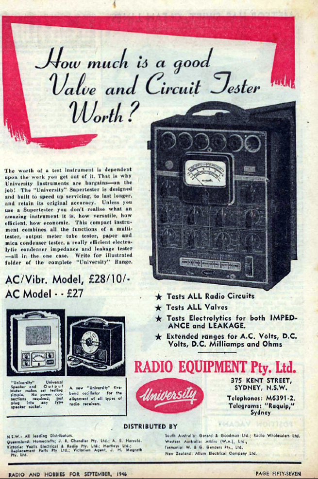
Thanks everyone. I found a Supertester on EBay for $600, a few subtle differences but that's without a doubt the one! It makes the $30 I paid for mine seem quite reasonable. I don't mind not having the multimeter section one little bit. Kevin Chant even has the manuals though after a quick look I'm still not so sure about the E switch. I'll download his circuit and compare. |
|
|
Return to top of page · Post #: 12 · Written at 10:50:24 PM on 17 June 2013.
|
|
|
|
Location: Sydney, NSW
Member since 28 January 2011 Member #: 823 Postcount: 6956 |
|
I wonder if they made a compact version. |
|
|
Return to top of page · Post #: 13 · Written at 1:04:48 PM on 18 June 2013.
|
|
|
|
Location: Melbourne, VIC
Member since 20 September 2011 Member #: 1009 Postcount: 1263 |
|
The E switch is for- |
|
|
Return to top of page · Post #: 14 · Written at 6:28:22 PM on 18 June 2013.
|
|
|
|
Location: Blue Mountains, NSW
Member since 10 March 2013 Member #: 1312 Postcount: 401 |
|
The case isn't a knocked together job but is different to the one on Ebay. It's got very fine finger joints down each corner with a tiny dowel to lock them in, it looks professionally made. It's longer than shown in the photo with a storage section below the tester panel but the divider between this section and the guts of the tester doesn't look original. The whole box doesn't look quite right to be original to this tester. It's possible the panel's been cut but it's an extraordinary job if it was. I think it's an enamelled panel but no signs of chipping along the bottom edge. It does look ever so slightly different to the other three sides If it's cut, I'm impressed! |
|
|
Return to top of page · Post #: 15 · Written at 9:34:33 AM on 19 June 2013.
|
|
|
|
Location: Canberra, ACT
Member since 23 August 2012 Member #: 1208 Postcount: 587 |
|
The D^D and other indications are a pretty strong clue that this would have been a variant of the commercial version, supplied on contract to a particular specification for the military. There used to be a Department of Supply that issued tenders for such things, and they had a habit of not buying things off the shelf. The sturdy cabinet-work is also probably a special spec. |
|
|
You need to be a member to post comments on this forum.
|
|
Sign In
Vintage Radio and Television is proudly brought to you by an era where things were built with pride and made to last.
DISCLAIMER: Valve radios and televisions contain voltages that can deliver lethal shocks. You should not attempt to work on a valve radio or other electrical appliances unless you know exactly what you are doing and have gained some experience with electronics and working around high voltages. The owner, administrators and staff of Vintage Radio & Television will accept no liability for any damage, injury or loss of life that comes as a result of your use or mis-use of information on this website. Please read our Safety Warning before using this website.
WARNING: Under no circumstances should you ever apply power to a vintage radio, television or other electrical appliance you have acquired without first having it checked and serviced by an experienced person. Also, at no time should any appliance be connected to an electricity supply if the power cord is damaged. If in doubt, do not apply power.
Shintara - Keepin' It Real · VileSilencer - Maintain The Rage