Welcome to Australia's only Vintage Radio and Television discussion forums. You are not logged in. Please log in below, apply for an account or retrieve your password.
Australian Vintage Radio Forums
  Home  ·  About Us  ·  Discussion Forums  ·  Glossary  ·  Outside Links  ·  Policies  ·  Services Directory  ·  Safety Warnings  ·  Tutorials

Tech Talk

Forum home - Go back to Tech talk

 Bell 5B5 with an EL41
« Back · 1 · Next »
 Return to top of page · Post #: 1 · Written at 8:20:24 PM on 10 June 2013.
Scraps's Gravatar
 Location: Blue Mountains, NSW
 Member since 10 March 2013
 Member #: 1312
 Postcount: 401

I'm nearly finished restoring a Bell 5B5 chassis (don't ask why, it's mainly for the learning experience!). It's got surprisingly good sound for such a basic radio but while doing my final checks I've discovered things are not quite right. All paper and electro caps were replaced as well as resistors measured and replaced if necessary.

I don't have the circuit for the 5B5 but I did get hold of one for a 5B4. Apart from the layout of the chassis being completely different, the circuit appears to be identical. I DO believe Marc's monkey has worked on this chassis at some in the past, mostly around the HT and EL41 OP valve. I won't go into all the details, the worst was a 10K 5W resistor in the HT instead of a 1K 5W which I figure would have dropped the HT to about 0 volts. My problem now is the HT is 170v when it should be 210v. It's also drawing about 75ma when it should be about 50. Using Marc's "start at the AF" advice I've found the EL41 OP valve has 10.6v bias which should be around 7v and is drawing 68ma across the cathode resistor which I think should be around 35ma.

Shorting the plate of the previous stage to earth and bypassing the grid resistor both cause the HT to rise to normal which I think indicates internal leakage in the EL41. The rest of the HT is only drawing 15ma.

What I can't figure out, and I hope I get the terminology right, is what the value of the grid coupling resistor should be. The coupling capacitor is shown as 0.005μF and tested ok but I replaced it anyway with a new (tested) 0.005μF. The grid resistor is shown as 500k and had a 470k fitted which measured 620k – it was replaced. The coupling resistor is shown as being 560 ohms and had a 7.4k fitted. I’ve replaced this with a 560 ohm but other similar 6M5 circuits I’ve seen usually have something closer to 50k in here. Is this possibly a misprint and should it be a 56k resistor? Someone’s obviously been tinkering here. I can’t measure any voltage on the grid (even if there was I suspect it disappears as soon as I put the DVM on it) but could a lower value resistor here cause excessive plate current mimicking a leaky valve? How would I work out what value the coupling resistor should be?

I very much doubt I’d find an EL41 in Australia, even if I did it’d cost more than the radio’s worth. I don’t want to go to the trouble of modifying it for a 6M5 or 6BQ5 if it’s just that resistor being wrong.

Cheers,

Warren


 Return to top of page · Post #: 2 · Written at 9:22:20 PM on 10 June 2013.
MonochromeTV's avatar
 Location: Melbourne, VIC
 Member since 20 September 2011
 Member #: 1009
 Postcount: 1179

The EL41 is indeed electrically identical to the 6M5. Rimlock & Locktal valves were quite common in NZ, though I have never seen them in Australian made radios. Do you have the means to test the valve? Or maybe you could source one from NZ. What about the rectifier valve - do you know if that is working properly? Again, if the rectifier is a Rimlock type (EZ40 something) it will be electrically the same as a 6V4.

Cheers


 Return to top of page · Post #: 3 · Written at 9:45:15 PM on 10 June 2013.
Scraps's Gravatar
 Location: Blue Mountains, NSW
 Member since 10 March 2013
 Member #: 1312
 Postcount: 401

I don't have any way to test the EL41 apart from the current. Specs I found show it should be a total of around 40mv and this ones drawing about 75ma through the cathode resistor. The rectifier is indeed an EZ40, I'm assuming it's ok because effectively grounding the grid on the EL41 brings the HT up to spec.

I did read that 6M5/EL41's are prone to this problem in old age but I want to make sure about that resistor. I don't really want to spend too much chasing an EL41, if it's definitely the valve I'll try and find a 6M5 or 6BQ5. I don't really care about originality on this chassis, I'm treating it as a learning experience. I'm actually glad I've finally got one with a genuine fault to chase.

Cheers,

Warren


 Return to top of page · Post #: 4 · Written at 11:10:13 PM on 10 June 2013.
Marcc's avatar
 Location: Wangaratta, VIC
 Member since 21 February 2009
 Member #: 438
 Postcount: 5239

The terminology is a worry. What is needed is for us to see a circuit, to stop some speculating.

Low B+ indicates an overload. One does not short plates to ground. Clearly if it was the plate that was shorted the volts should fall . The voltage rises with loss of tube conduction.

The vast majority of sets do not have a coupling resistor? If you look at a 6V6, 6F6, circuit you may find that the grid has two resistors 500K (grid leak) from chassis, or Neg, to a 50K grid stopper that goes to the grid and those resistors have an attrition rate. I have repalced two lots this week (one lot on a 6v6 one lot on an EL333A).

The coupling capacitor then goes between the grid stopper and the grid leak.

Philips list EL41 as electrically (not pin) equivalent to 6CK5.

I have used 6CK6 (Video OP) in place of a 6M5 but there is a trap. To use a 6CK6 you must connect pin 6 to the cathode pin 3

Do check if you are reading the pinouts of the valves correctly. You could remove the EL41 & see where the voltage ends up? If you use a meter with IC clips, you can monitor the volts & switch the radio off as soon as you get a terminal HT reading.

Marc


 Return to top of page · Post #: 5 · Written at 11:38:00 PM on 10 June 2013.
Scraps's Gravatar
 Location: Blue Mountains, NSW
 Member since 10 March 2013
 Member #: 1312
 Postcount: 401

Thanks Marc, I've sent a copy of the relevant part of the circuit to Brad.

I'm really not sure of the terminology. The plate I shorted to ground was the EBC41, certainly not the EL41. I also bypassed what I think you called the grid leak resistor (500K). Both of these actions caused the HT to rise to normal.

The 560 ohm resistor on the grid (grid stopper?) is the one I'm not so sure about. I'm thinking it should be much larger.

Cheers,

Warren


 Return to top of page · Post #: 6 · Written at 3:43:32 PM on 11 June 2013.
Marcc's avatar
 Location: Wangaratta, VIC
 Member since 21 February 2009
 Member #: 438
 Postcount: 5239

I do really need to see the circuit. Check that the 500K resistor on the grid is not open.

If the valve looses grid bias it becomes a diode and will pretty much be a short circuit. I need to see if EL41 has a cathode resistor. They often have a cap across them, if it shorts, self bias on the valve is lost.

Marc


 Return to top of page · Post #: 7 · Written at 4:34:31 PM on 11 June 2013.
Scraps's Gravatar
 Location: Blue Mountains, NSW
 Member since 10 March 2013
 Member #: 1312
 Postcount: 401

Just waiting on Brad to upload the circuit, it might all make a bit of sense then. There is a 150 ohm cathode resistor to ground, no parallel cap. I measured 10.5v across it.

The numbers in red are the component values that were in the circuit before replacement.

Warren

Bell 5B4 Circuit Diagram


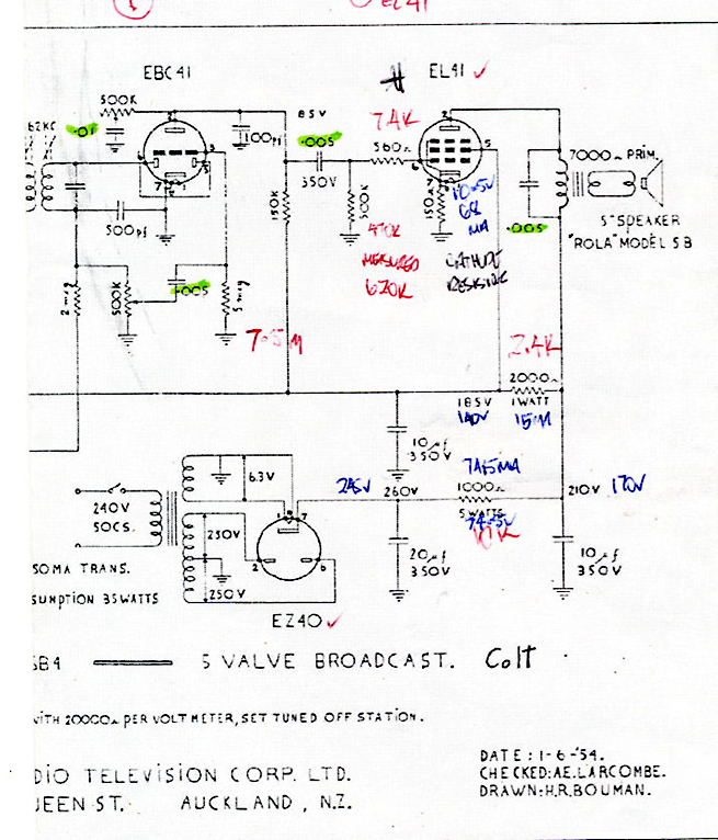
 Return to top of page · Post #: 8 · Written at 8:50:23 PM on 11 June 2013.
Brad's avatar
 Administrator
 Location: Naremburn, NSW
 Member since 15 November 2005
 Member #: 1
 Postcount: 7290

All done. Just got back from a camping trip last night, hence the delay.


‾‾‾‾‾‾‾‾‾‾‾‾‾‾‾‾‾‾‾‾‾‾‾‾‾‾‾‾‾‾‾‾‾‾‾‾‾‾‾‾‾‾‾‾‾‾‾‾‾‾‾‾‾‾‾‾‾‾‾‾‾‾‾‾‾‾‾‾
A valve a day keeps the transistor away...

 
 Return to top of page · Post #: 9 · Written at 11:31:05 PM on 11 June 2013.
Marcc's avatar
 Location: Wangaratta, VIC
 Member since 21 February 2009
 Member #: 438
 Postcount: 5239

You can find the more detailed valve data on Franks Electron tube pages.

I am thinking you have a short in the EL41, or a wire or debris short.

The Bible says that 6CK5 / EL41 at 250V plate should draw 36mA plate & 5.2mA screen total 41.2mA giving about 6.2V across the cathode resistor. Your set quotes a 210V B+ rail.. So perhaps 6V is more realistic.

I see part of a quoted transformer current on the schematic what was that in full

Marc


 Return to top of page · Post #: 10 · Written at 8:16:15 AM on 12 June 2013.
Scraps's Gravatar
 Location: Blue Mountains, NSW
 Member since 10 March 2013
 Member #: 1312
 Postcount: 401

Not much missing, it just says "50ma Trans, Power consumption 35 watts.

I hadn't considered debris although if I bypass the 500k resistor to ground, HT rises to normal. I'll carefully check the underside if the EL41 socket, the whole chassis was coated in the thickest layer of stearate I've ever seen, it took hours to clean with particular attention to the sockets. I wonder if stearate is conducive.

Warren


 Return to top of page · Post #: 11 · Written at 9:29:53 AM on 12 June 2013.
Marcc's avatar
 Location: Wangaratta, VIC
 Member since 21 February 2009
 Member #: 438
 Postcount: 5239

I am still thinking that thre is something seriously wrong with, or around that output tube.

If anything in the secondary circuit of the OP transformer goes open, the transformer may "ring" and that will generate EHT and you will get a "flashover" like a spark plug.

Some valves had silver on their pins, which was a serious oversite. It grows whiskers like your face & shorts or it causes tracking.

If you used anything aqueous, cleaning, then water can remain in the wafers of some sockets. If you used an alkaline product like soda ash, automotive aluminium wheel cleaner, or caustic? That will form Sodium Stearate: Soap. Soap left behind holds water. Only pure distilled water does not conduct electricity.

If you have not replaced those grid resistors yet: Do it. As I fix commercially any resistor that is not within 10% is replaced. The 11-7 Kriesler (still on the bench here) has had nine replaced.

It cannot be expected to work properly with parts that have failed, or are are out of spec.

Marc


 Return to top of page · Post #: 12 · Written at 9:49:37 AM on 12 June 2013.
Scraps's Gravatar
 Location: Blue Mountains, NSW
 Member since 10 March 2013
 Member #: 1312
 Postcount: 401

Yep, soda ash. I think I'll disconnect a few things around the EL41 socket and put my Megger on it.

Both the grid resistors were replaced as well as the cathode resistor. I'm still suspicious about the 560 ohms resistor, it seems a very low value specified for there. Other similar circuits have something closer to 50k. It had a 7.4k in there originally.

Warren


 Return to top of page · Post #: 13 · Written at 7:54:11 PM on 12 June 2013.
Marcc's avatar
 Location: Wangaratta, VIC
 Member since 21 February 2009
 Member #: 438
 Postcount: 5239

Do note that the 560R Grid stopper resistor is probably low because the coupling cap is. It is important that it stays as the factory built it. Introducing new, different parts may cause difficulties

Marc


 Return to top of page · Post #: 14 · Written at 1:18:37 PM on 15 June 2013.
Scraps's Gravatar
 Location: Blue Mountains, NSW
 Member since 10 March 2013
 Member #: 1312
 Postcount: 401

OK, this got moved to the side of the bench whilst I tinkered with a recently purchased valve tester but that's another story I need to ask a few questions about. Unfortunately it doesn't have a rimlock socket.

With a few jumpers and careful setup I've substituted a Sovtek 6BQ5 for the EL41. 6BQ5's not quite right here but very close and all I had to hand. The OPT impedance on this radio is 8.7k, I think the 6BQ5 would prefer closer to 5k.

The results; B+ up from 170v to 235v (spec 210V) plate voltage is 216v. Screen up from 140v to 208v (spec 185v). Cathode is 6.3v down from 10.5v. Voltage across the 1k 5w was 47.5v.

All in all I'm quite happy that this proves the EL41 has internal leakage. I've actually found a local supplier that has a "good" used EL41 so I'll wait for that to turn up and see how "good" it actually is.

Cheers,

Warren


 Return to top of page · Post #: 15 · Written at 9:46:30 PM on 15 June 2013.
Marcc's avatar
 Location: Wangaratta, VIC
 Member since 21 February 2009
 Member #: 438
 Postcount: 5239

I think leakage is not the term. The voltages were consistent with a dirty great short.

It is likely with a high load & wrong bias for it output valve, that it is not drawing enough current, raising the volts. Which does prove a point.

Different meters than used originally, presenting different loads, will give differing readings. That should not apply to B+. A variance of 20% is considered normal and there should now be no leaky caps dragging the voltage down.

The 11-7 on my bench is now running and prattling away in Mandarin, is also running slightly high at 244V not 230VThis is also because it came with a 6V6 in it not an EL33A.

Rather than buy a new valve I have adjusted the cathode resistor to try cutting 6V6 back to 36mA. This as the set is backbiased and the current through the backbias is critical to the rest of the sets bias. The current of the 6V6 could also have endangered the transformer.

The above is an example of why deviating from spec can have potentially serious ramifications.

Putting a good EL41 in your set should present a simple solution.

Marc


« Back · 1 · Next »
 You need to be a member to post comments on this forum.

Sign In

Username:
Password:
 Keep me logged in.
Do not tick box on a computer with public access.