
Tech Talk
Forum home - Go back to Tech talk
|
IF transformer - fixable or not?
|
|
|
Return to top of page · Post #: 1 · Written at 5:27:11 PM on 19 May 2013.
|
|
|
|
Location: Canberra, ACT
Member since 23 August 2012 Member #: 1208 Postcount: 587 |
|
By a lot of cautious prodding with a wooden stick, I think I have isolated the erratic volume-fade problem that has been bugging me for years on my Philips Radioplayer 123. It has recently got worse. |
|
|
Return to top of page · Post #: 2 · Written at 7:47:31 PM on 19 May 2013.
|
|

|
Location: Tamworth, NSW
Member since 6 April 2012 Member #: 1126 Postcount: 472 |
|
Maven |
|
|
Return to top of page · Post #: 3 · Written at 8:34:26 PM on 19 May 2013.
|
|

|
Location: Wangaratta, VIC
Member since 21 February 2009 Member #: 438 Postcount: 5720 |
|
It is quite possible to get wire breaks when changing caps & components on IF transformers & coils, often excerbated by the application of too much heat, or force |
|
|
Return to top of page · Post #: 4 · Written at 9:52:17 PM on 19 May 2013.
|
|
|
|
Location: Canberra, ACT
Member since 23 August 2012 Member #: 1208 Postcount: 587 |
|
|
|
|
Return to top of page · Post #: 5 · Written at 9:52:18 AM on 20 May 2013.
|
|
|
|
Location: Oradell, US
Member since 2 April 2010 Member #: 643 Postcount: 839 |
|
In America, the "K-tran" IF transformer was very popular, and they used a silver mica wafer that tends to fail. See my page of repair tips, scroll halfway down http://www.wa2ise.com/radios/repair.htm.   If your IF transformer looks something like this, you could try taking it apart. Be careful of the fine wire. And if you have to, you should be able to sub another IF transformer if it would physically fit. |
|
|
Return to top of page · Post #: 6 · Written at 10:23:35 AM on 20 May 2013.
|
|
|
|
Location: Canberra, ACT
Member since 23 August 2012 Member #: 1208 Postcount: 587 |
|
  Maven |
|
|
Return to top of page · Post #: 7 · Written at 7:48:13 PM on 20 May 2013.
|
|
|
|
Location: Wangaratta, VIC
Member since 21 February 2009 Member #: 438 Postcount: 5720 |
|
My Philips 132L is the one Brad had as radio of the week a few weeks back. 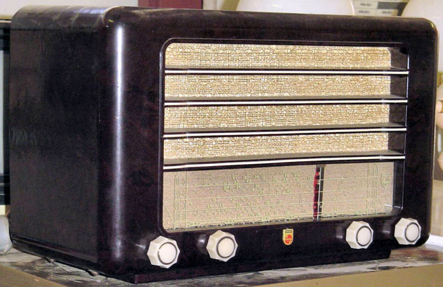 I have the Philips data which says IFT1 is CZ.320.421: IFT2 CZ.320.420. This is not what yours has. One is oblong with two adjusters top. They are shorter than the valves & held down by a spring clip similar in concept to those used to hold down valves. Yours have been swaged. You can likely fold the rim back to dismantle. Make sure all is marked (position of green dot) before dismanteling anything. Take a good look at the power transformer, thats the type that often have have wires exiting from the sides of the wrap. Marc |
|
|
Return to top of page · Post #: 8 · Written at 9:06:28 AM on 21 May 2013.
|
|
|
|
Location: Blue Mountains, NSW
Member since 10 March 2013 Member #: 1312 Postcount: 401 |
|
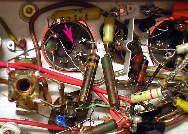
It may make no difference but I'd try the simple things first. The solder joint doesn't look so good, clean it up with soldering braid, clean the resistor lead and wire so they're shiny and resolder the joint. As I say, it mightn't fix it but at least eliminates the joint. |
|
|
Return to top of page · Post #: 9 · Written at 10:40:38 AM on 21 May 2013.
|
|
|
|
Location: Canberra, ACT
Member since 23 August 2012 Member #: 1208 Postcount: 587 |
|
I have redone the joint at lug 3. There's a bit of flux left on the base, which I can clean up later. I think the joint is firm, because there is no effect if I push down or sideways on the resistor, only if I push sideways on the lug itself, to the left. |
|
|
Return to top of page · Post #: 10 · Written at 4:41:57 PM on 21 May 2013.
|
|
|
|
Location: Wangaratta, VIC
Member since 21 February 2009 Member #: 438 Postcount: 5720 |
|
I have as said only found a broken cap once. There is the possibility (more common) that there is a wire break. Do make sure the resistor is OK. |
|
|
Return to top of page · Post #: 11 · Written at 7:21:21 PM on 21 May 2013.
|
|
|
|
Location: Tamworth, NSW
Member since 6 April 2012 Member #: 1126 Postcount: 472 |
|
Maven. |
|
|
Return to top of page · Post #: 12 · Written at 9:09:29 AM on 22 May 2013.
|
|
|
|
Location: Wangaratta, VIC
Member since 21 February 2009 Member #: 438 Postcount: 5720 |
|
Under the heading "Seen it": |
|
|
Return to top of page · Post #: 13 · Written at 5:19:32 PM on 22 May 2013.
|
|
|
|
Location: Canberra, ACT
Member since 23 August 2012 Member #: 1208 Postcount: 587 |
|
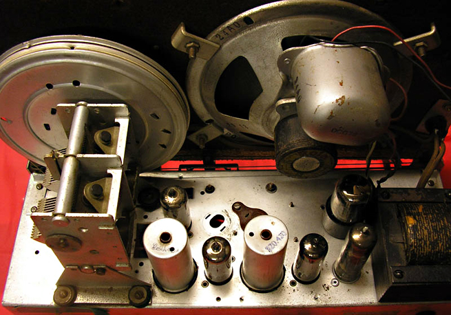
OK, I've gone to the next stage on this. I removed the IF-1 can and opened it by working around the swaged rim just enough to release the base. In side I found the whole assembly was slathered in what looks like beeswax. 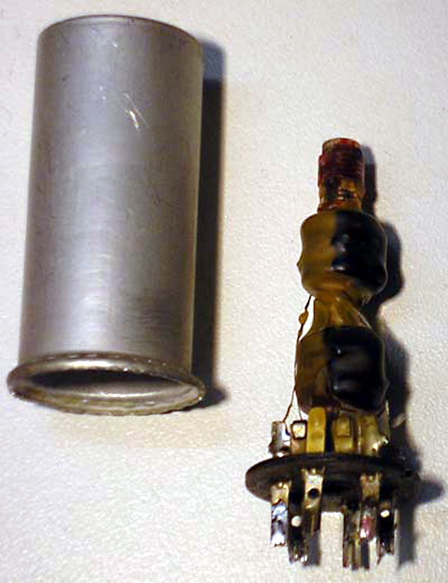 When I carefully touched the wire leading from lug 3 to the coil, it parted. The wax has several obvious cracks in some places, I believe likely due to changes in temperature over. The wax layer over the tiny 5-strand copper wire has probably reduced the flexibility and created a point that concentrated all the normal flexing and eventually broke, as copper flexes can do at plug entries, for example. It was quite difficult to repair. I took about 2cm of similar fine stranded copper wire and tinned the whole length of it with solder, then soldered it to the base lug. I carefully wiped the end of the wire leading to the coil with a soldering iron and a flux pen, trying to get rid of as much as possible of the wax and varnish insulation. The wire is very fragile and I didn't want to lose any more of it. Eventually I got a bond between the loose end and the end of the new tinned section. 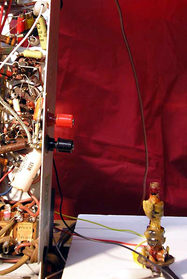 I checked that there was continuity on both coils. The repaired primary showed the rise and fall in resistance consistent with a capacitor in parallel circuit, and settled at 20ohm. The secondary settled at 12ohm, which is the specified rating for both coils. So the repaired coil has gained 8ohm through the repair joints - I don't know if that is significant or not. I set up the IF TX with double-ended test leads to put it back in circuit, out of the chassis. In the photo, you can see the leads at the chassis top left, and you can just see the tinned section of repair wire bottom right. The radio functions exactly as before, with fluctuating volume affected by duration of service and by spikes in the power circuit - eg switch on/off - but I'm wondering if this might be a secondary effect of those spikes sending a RF pulse through the RF circuit. Many questions now: 1. Is there a safe way to remove the wax to read those mica cap values, and should the wax be replaced in some way? 2. Should I proceed to replace the internal mica caps? 3. The resistor R3 between lug 3 and V1 is specified as 30kR, but reads 40kR - does that matter? 4. Should I be just replacing a whole lot more components while the chassis is on the bench? So far, only the higher-value capacitors have been replaced. Maven |
|
|
Return to top of page · Post #: 14 · Written at 6:00:19 PM on 22 May 2013.
|
|
|
|
Location: Wangaratta, VIC
Member since 21 February 2009 Member #: 438 Postcount: 5720 |
|
Do remember that the wire on those coils is insulated and that needs to be scraped off. |
|
|
Return to top of page · Post #: 15 · Written at 8:33:29 PM on 22 May 2013.
|
|

|
Location: Sydney, NSW
Member since 28 January 2011 Member #: 823 Postcount: 6956 |
|
A thump sound at switch off can be attributed to bad IF caps (particularly in Philips sets according to a mate of mine). |
|
|
You need to be a member to post comments on this forum.
|
|
 Marc
MarcSign In
Vintage Radio and Television is proudly brought to you by an era where things were built with pride and made to last.
DISCLAIMER: Valve radios and televisions contain voltages that can deliver lethal shocks. You should not attempt to work on a valve radio or other electrical appliances unless you know exactly what you are doing and have gained some experience with electronics and working around high voltages. The owner, administrators and staff of Vintage Radio & Television will accept no liability for any damage, injury or loss of life that comes as a result of your use or mis-use of information on this website. Please read our Safety Warning before using this website.
WARNING: Under no circumstances should you ever apply power to a vintage radio, television or other electrical appliance you have acquired without first having it checked and serviced by an experienced person. Also, at no time should any appliance be connected to an electricity supply if the power cord is damaged. If in doubt, do not apply power.
Shintara - Keepin' It Real · VileSilencer - Maintain The Rage