|
Leader LSG-11
|
|
|
|
|

|
Location: Blue Mountains, NSW
Member since 10 March 2013
Member #: 1312
Postcount: 401
|
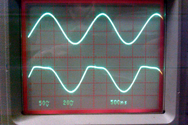
Hi, the output of my Leader LSG-11 signal generator is not the perfect sine wave I would have hoped for, the negative part is clipped and flattened.
I got a circuit from Kevin Chant's website (thanks again Kevin!) and think I've narrowed down where the problem starts with C12 which is on the screen input to the oscillator from the tuning capcitors. I was hoping someone might be able to confirm my diagnosis before swapping C12 as it's in a bugger of a spot that's going to require some serious dismantling to get to it.
I can't see anything else that could cause the distortion as it only goes to the grid but someone that understands this more than I might spot something obvious.
The 15K R11 on the screen is at 18.8K. Apart from the size and Foxohm brand the only other marking is an "H' after the 15K so I don't know what the tolerance of this resistor is. In any case, correcting the value using external resistors reduced the amplitude but did nothing for the clipping.
I'm sending Brad a scope trace, the top is the tuning capacitor side of C12 and the bottom is the oscillator side of C12. It occurred to me that I might be attenuating the signal by having the scope here but removing the leads and scoping the output makes no difference.
Cheers,
Warren
|
|
|
|
|

|
Location: Wangaratta, VIC
Member since 21 February 2009
Member #: 438
Postcount: 5703
|
I actually have one of those. Without modification it is a potential death trap.
This is liable to be fitted with a two wire mains cable and has two filter caps viz C18 & 19 that are connected to the metal body of the apparatus. Should one of those fail, the metal body (case) can become "alive".
Replace the power cable with a three wire one earthing the chassis. Remove C18 &19, or replace with mains approved "X" types.
I have a suspicion that that it had either oil filled, or wax paper capacitors in it. I replaced all of them. Wax paper caps leak and the electrolytics will be drying out. If yours has that sort of cap, I would suggest the same action.
A 12mm gland fitted backwards will hold the new mains cable more neatly.
One of the issues with them is the low B+ voltage used, which from memory was only around 120V. That was not well thought out, as that puts the operating point right on the "knee" of the valves curve.
By operating on the "knee point" you run the risk of the positive & negative excursions being different.
Consider these thoughts
Marc
|
|
|
|
|
|
|
Location: Blue Mountains, NSW
Member since 10 March 2013
Member #: 1312
Postcount: 401
|
Replacing the two core mains with three core flex and grounding the chassis was the first thing I did. I didn't think of reversing a gland, I fitted a new grommet and anchored it with a cable tie instead.
This is liable to be fitted with a two wire mains cable and has two filter caps viz C18 & 19 that are connected to the metal body of the apparatus
I was a bit worried about those two, they look like just standard ceramic discs. The circuit shows them as 0.001μF, the only X types I can easily lay my hands on are 0.010μF. Is the value critical?
I have a suspicion that that it had either oil filled, or wax paper capacitors in it
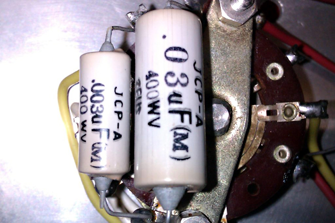
I think they're oil filled, they look like small electrolytics but no polarity, I haven't seen these before but I think I'll carefully replace them (PCB's?)
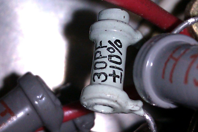
The pF caps are a strange very small tubular type like tiny old wire wound resistors, again I haven't seen these before (photo attached)
The circuit I got from Kevin shows the B+ voltage as 75V. Not really knowing how to approach a signal generator I treated it as an old radio and after removing the valves and a visual inspection, powered it up whilst measuring the voltage. The B+ climbed to about 220V and gave me a fright. After removing power it very, very slowly drops, I think this means the electro's aren't too bad. It's only got about 600mv ripple and a couple of new electros clipped to it didn't improve this much but I'll still replace them. I spent the best part of the next hour trying to figure out why it was so high and decided it was because it's not loaded. With the valves back in it again went up to about 215V but as they warmed up dropped back down to 76V.
By operating on the "knee point" you run the risk of the positive & negative excursions being different
I think I understand that, but could it cause clipping? I was hoping that because it gets clipped on the screen input to the oscillator that it wasn't a valve problem. I can't remember where I set the ground for the bottom trace but I might check all of them again.
I've got some bits on order so I'll have to move this to the side of the bench til next week.
Cheers,
Warren
|
|
|
|
|
|
|
Location: Wangaratta, VIC
Member since 21 February 2009
Member #: 438
Postcount: 5703
|
Rod Champness featured one of these in in an article on them some time ago, in Silicon Chip.
Any of the caps on B+ and plates will drag down the B+ if they are leaking. I would have checked the ones in mine with an insulation tester (around their rated voltage) on deciding things were not quite right. Having years of experience with radio's, gives one the experience also, in knowing which caps are unreliable and are to be tossed out on sight.
Also check the 3K resistor R13. Check the wiring of the 6AR5, I find the screen comment odd. According to my circuit that valve is "triode wired" : The screen is tied to the plate.
If the rectifier is as per circuit & is selenium. They are notorious, for failing & creating clouds of toxic waste. Might pay to measure the voltage drop across it.
Naturally voltages are not given on the circuit, but I could possibly find a space & measure; servicing bench is cluttere with a Philips 115B
Marc
|
|
|
|
|

|
Location: Sydney, NSW
Member since 28 January 2011
Member #: 823
Postcount: 6946
|
Rod Champness featured one of these in in an article on them some time ago, in Silicon Chip.
Perhaps this one:
June 2005 "Signal Generators: What They Are And How To Fix Them"
I have an LSG-11.Somebody put a 3 pin plug on it. Guess I'd better open it up and take a good look around.
|
|
|
|
|
|
|
Location: Blue Mountains, NSW
Member since 10 March 2013
Member #: 1312
Postcount: 401
|
Thanks for your help. Oops, I wasn't very clear on my first post. The scope trace is on both sides of C12 on the screen input on the RF oscillator side of the 12BH7. I'm forgetting there's two oscillators, I haven't looked at the AF yet.
A good lesson for me on using old diagrams. The 75v is a handwritten notation and might be what somebody found, not what they expected!
Yes it does have the selenium diode, I didn't measure the voltage drop across it but I did try swapping a 1N4004 which didn't change the voltage. Toxic smoke? I think I'll toss the selenium and put the 1N4004 back.
I'll see if I can find the article although not being a subscriber only the first page will be accessible.
I do have my Grandfather's old Megger but have never used it on capacitors. I'll have to check what the voltage settings are, I haven't used it for years. Is this suitable for testing them?
Cheers, Warren
|
|
|
|
|
|
|
Location: Wangaratta, VIC
Member since 21 February 2009
Member #: 438
Postcount: 5703
|
Those caps with pF on them are ceramic they like Australian silver Mica's rarely fail.
The axials with 0.03 etc. look very much like the oil filled type. The Megger will test them, BUT, some of them put out a fixed 500VDC. They should never be used on electrolytics.
The one I use is an Altronics Insulation tester, which has adjustable voltages. The circa 1938 VCT that I have also has a cap test function. The voltage applied should never exceed the cap rating.
For reference VCT uses just a simple neon tube with appropriate resistor, run on about 225V DC. Theoretically this "Neon flash test" gives a brief flicker when connected and the intensity of the glow indicates how bad the leakage: A good cap should not leak.
If the rectifier is working, it ain't broke, do not fix.
GTC: Probably a wise move. Unless you actually see it for yourself , or measure the bonding between the earth on the mains plug & chassis: You will never know if it has been done correctly.
Some of the things I see are scary. The Philips on the bench came with the original plug & 2 wire rubber mains cord. It is cracked from start to finish.
Marc
|
|
|
|
|
|
|
Location: Blue Mountains, NSW
Member since 10 March 2013
Member #: 1312
Postcount: 401
|
The clipped sine wave is on the grid side of that 30pf capacitor (C12) but it sounds like I've got a few voltage and potentially nasty capacitor issues to sort out first.
Marc, if you get a chance in the next week or so to measure the B+ I'd greatly appreciate it. If it is around 120v then mine's a long way off.
|
|
|
|
|

|
Administrator
Location: Naremburn, NSW
Member since 15 November 2005
Member #: 1
Postcount: 7618
|
Some of the things I see are scary. The Philips on the bench came with the original plug & 2 wire rubber mains cord. It is cracked from start to finish.
Not to mention the several Ebay sellers who still plug these appliances in anyway and boast about it in their sales.
I also remember Peter Lankshear describing a radio restoration in Electronics Australia years ago that was fitted with a mains plug - the set was a battery model and the mains plug was to feed an extension speaker. I've personally seen similar potentially hazardous modifications.
Unfortunately, stupidity isn't restricted to our humble hobby. Back in 1994 I was running my own electrical business and a punter demanded that I fit his whole home with 50 watt halogen downlights. I had a company policy of not fitting these as I believed they were a fire hazard (and still do believe this to be the case). I also told him that his electric light bill would go through the roof despite his argument that "low voltage" also meant "low power". He didn't do the sums though, the job was to install about 6kW of lighting and extra circuits would have been required because the maximum number of points allowed on a domestic final sub-circuit is twenty.
The final nail in the coffin was his request that to lower his costs I was to wire the lights in with figure-8 speaker wire rather than 1.5mm2 TPS cable as required by the SAA Wiring Rules. If I'd have done the job as requested I would have burnt his house to the ground and lost my licence in the process. With that, I just refused to have him as a customer because he would not be reasoned with.
‾‾‾‾‾‾‾‾‾‾‾‾‾‾‾‾‾‾‾‾‾‾‾‾‾‾‾‾‾‾‾‾‾‾‾‾‾‾‾‾‾‾‾‾‾‾‾‾‾‾‾‾‾‾‾‾‾‾‾‾‾‾‾‾‾‾‾‾
A valve a day keeps the transistor away...
|
|
|
|
|
|
|
Location: Wangaratta, VIC
Member since 21 February 2009
Member #: 438
Postcount: 5703
|
Right! In between jobs ... a rush job. I opened up the leader & took a look.
Range D Modulation on. Note this is a Transmitter, not a radio.
B+ after rectifier (original selenium) abt 112V (I did say low) 73V DC after 3K
Voltage on plate of 6AR5 43V.
Non of those oil type caps in the set. Either Red 630VDC Greencaps or axial 630V Metalised Polypropylene. All original ceramic caps, not touched. Orignal 10 x 10mfd Doublet Electrolytic still in place.
CRO:..Sine wave at plate of 6AR5, true undistorted sine wave. Modulation envelope looks to be as it should. What is in the photo is not the modulation envelope.
I would toss all of the oil type caps (as suggested) and see where it all is after that. Leaking coupling caps can seriously impinge on the valve bias and that can easily result in distortion.
We will shy away from valve issues at this point. Lets fix the obvious & known first.
Marc
|
|
|
|
|
|
|
Location: Blue Mountains, NSW
Member since 10 March 2013
Member #: 1312
Postcount: 401
|
Thanks for that Marc, I've just checked mine and measured as follows;
Range D Modulation on
B+ after rectifier 105V
70V DC after 3K
Voltage on plate of 6AR5 42V
Sine wave on the plate of 6AR5 is good on the 1000Hz range, about 5v pp but the envelope has about 170mv of 50Hz ripple.
On the 400Hz range there is no sine wave, just a jagged 170mv 50 Hz ripple - this is a problem I wasn't aware of!
I find the schematic of the EXT-400-1000-XTAL switch very confusing and am not sure of which position it's shown in. I metered the switch by manually checking the action of the wipers, it all seemed OK but I'd better do a more thorough check later.
Just out of curiosity I checked the RF output on the front panel and found a perfect sine wave. I switched from range D to range C and once again had the clipped sine wave. At this point I changed back to range D and now had a clipped sine wave on range D as well. I haven't looked at the circuit yet but I suspect I charged up a crook capacitor by changing ranges.
I think I'll wait til the new caps arrive and are fitted before I chase this too much further.
Warren
|
|
|
|
|
|
|
Location: Wangaratta, VIC
Member since 21 February 2009
Member #: 438
Postcount: 5703
|
While those oil filled caps are in situ, I consider it a waste of time fault finding. That switch just might be dirty.
At a quick glance it is the 0.03 and 0.003 cap near the choke, on the diagram, that would be responsible for the frequency. Looks a bit like it could be a "Miller" transitron osc. I would expect the 0.03 to be the worst leaker.
If you had a frequency counter, it would be just, academic, but I would doubt that the audio frequencies would be correct. The CRO can measure frequency.
Hum on the B+ should be able to be seen by the CRO. On the basis that it is appearing, I think new filters are in order. You just might havea heater cathode leakage / short issue as well, but we will not go there yet.
Voltage variance of 20% is considered normal leaking caps will drag the voltage down. I do not believe voltage is the issue, as mine is working with voltages close to yours.
Again, sit on the fingers until you get rid of those oil caps.
Marc
|
|
|
|
|
|
|
Location: Wangaratta, VIC
Member since 21 February 2009
Member #: 438
Postcount: 5703
|
Just reviewing: What has to be dismantled? We are not touching the ceramics yet.
To get the solder off ( and clearing the terminals is good practice) Jaycar & others sell "solder wick". For valve work 3.2mm Goot, is what I would recommend.
Whist axials are generally the best for replacing the wax paper & oil type axials, the red greencap in some cases take up less space. In the case of the sub chassis up high that is a place I used a red greencap.
Marc
|
|
|
|
|
|
|
Location: Blue Mountains, NSW
Member since 10 March 2013
Member #: 1312
Postcount: 401
|
The tricky one to get to is the little 30pf ceramic on the grid of the 12BH7 on the sub chassis. Good sine wave on the input and clipped on the grid side (previous scope trace). Lots of other caps to replace first before I get back to looking at this one again. They haven't come today so might not arrive til next week.
Warren
|
|
|
|
|
|
|
Location: Wangaratta, VIC
Member since 21 February 2009
Member #: 438
Postcount: 5703
|
As previously indicated. The Ceramic & Mica caps are normally quite reliable. At this point I see no reason to change them.
I am still of the opinion that the oil filled types and electrolytics are the principal issue.
Marc
|
|
|
|
|
|
You need to be a member to post comments on this forum.
|