
Tech Talk
Forum home - Go back to Tech talk
|
Trimmer capacitors
|
|
|
« Back ·
1 ·
Next »
|
|
|
Return to top of page · Post #: 1 · Written at 2:37:53 PM on 22 August 2011.
|
|
|
|
Location: Melbourne, VIC
Member since 5 October 2009 Member #: 555 Postcount: 470 |
|
In one of my radios, the trimmer capacitors (10 to 40 pF) are cylindrical in shape, 10mm in diameter and 8 mm high. Each has a circular cap on top with a central adjusting screw. Paint or wax (??) has been daubed on the screw and sometimes down the side of the cap. 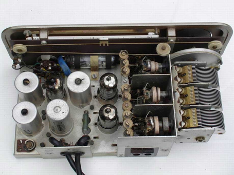 ‾‾‾‾‾‾‾‾‾‾‾‾‾‾‾‾‾‾‾‾‾‾‾‾‾‾‾‾‾‾‾‾‾‾‾‾‾‾‾‾‾‾‾‾‾‾‾‾‾‾‾‾‾‾‾‾‾‾‾‾‾‾‾‾‾‾‾‾ Cheers, Ian |
|
|
Return to top of page · Post #: 2 · Written at 3:19:09 PM on 22 August 2011.
|
|

|
Administrator
Location: Naremburn, NSW
Member since 15 November 2005 Member #: 1 Postcount: 7612 |
|
G'day Ian, ‾‾‾‾‾‾‾‾‾‾‾‾‾‾‾‾‾‾‾‾‾‾‾‾‾‾‾‾‾‾‾‾‾‾‾‾‾‾‾‾‾‾‾‾‾‾‾‾‾‾‾‾‾‾‾‾‾‾‾‾‾‾‾‾‾‾‾‾ A valve a day keeps the transistor away... |
|
|
Return to top of page · Post #: 3 · Written at 8:55:52 PM on 22 August 2011.
|
|

|
Location: Wangaratta, VIC
Member since 21 February 2009 Member #: 438 Postcount: 5693 |
|
If it's the plasic encapsulated type (photo will confirm) with two screws at the base holding it down. Only the top adjusting screw moves & you should be able to see the top plate move. |
|
|
Return to top of page · Post #: 4 · Written at 10:28:47 PM on 22 August 2011.
|
|
|
|
Administrator
Location: Naremburn, NSW
Member since 15 November 2005 Member #: 1 Postcount: 7612 |
|
Photo added. ‾‾‾‾‾‾‾‾‾‾‾‾‾‾‾‾‾‾‾‾‾‾‾‾‾‾‾‾‾‾‾‾‾‾‾‾‾‾‾‾‾‾‾‾‾‾‾‾‾‾‾‾‾‾‾‾‾‾‾‾‾‾‾‾‾‾‾‾ A valve a day keeps the transistor away... |
|
|
Return to top of page · Post #: 5 · Written at 10:06:38 AM on 23 August 2011.
|
|
|
|
Location: Melbourne, VIC
Member since 5 October 2009 Member #: 555 Postcount: 470 |
|
Thanks guys, ‾‾‾‾‾‾‾‾‾‾‾‾‾‾‾‾‾‾‾‾‾‾‾‾‾‾‾‾‾‾‾‾‾‾‾‾‾‾‾‾‾‾‾‾‾‾‾‾‾‾‾‾‾‾‾‾‾‾‾‾‾‾‾‾‾‾‾‾ Cheers, Ian |
|
|
Return to top of page · Post #: 6 · Written at 7:54:07 PM on 23 August 2011.
|
|
|
|
Administrator
Location: Naremburn, NSW
Member since 15 November 2005 Member #: 1 Postcount: 7612 |
|
These trimmers were found in many kits published by the electronics magazines right up to the 1990's and are probably still sold today at Jaycar. They are pretty much built like a traditional tuning condenser but they have thermoplastic insulators in place of an air dialectric due to their small size. ‾‾‾‾‾‾‾‾‾‾‾‾‾‾‾‾‾‾‾‾‾‾‾‾‾‾‾‾‾‾‾‾‾‾‾‾‾‾‾‾‾‾‾‾‾‾‾‾‾‾‾‾‾‾‾‾‾‾‾‾‾‾‾‾‾‾‾‾ A valve a day keeps the transistor away... |
|
|
Return to top of page · Post #: 7 · Written at 11:18:43 PM on 23 August 2011.
|
|
|
|
Location: Wangaratta, VIC
Member since 21 February 2009 Member #: 438 Postcount: 5693 |
|
I would only use the sig gen as a reference for the frequency. And that is not always neccessary. |
|
|
Return to top of page · Post #: 8 · Written at 9:50:54 AM on 24 August 2011.
|
|
|
|
Location: Melbourne, VIC
Member since 5 October 2009 Member #: 555 Postcount: 470 |
|
Thanks Brad and Marc, ‾‾‾‾‾‾‾‾‾‾‾‾‾‾‾‾‾‾‾‾‾‾‾‾‾‾‾‾‾‾‾‾‾‾‾‾‾‾‾‾‾‾‾‾‾‾‾‾‾‾‾‾‾‾‾‾‾‾‾‾‾‾‾‾‾‾‾‾ Cheers, Ian |
|
|
Return to top of page · Post #: 9 · Written at 8:30:40 PM on 24 August 2011.
|
|
|
|
Administrator
Location: Naremburn, NSW
Member since 15 November 2005 Member #: 1 Postcount: 7612 |
|
I usually recommend silicone spray for easing moving parts as this product does not attract dust the way oil based sprays do however I am not sure about the dialectric qualities of any lubricants and their application in this case may throw out the value of these trimmers quite a bit. ‾‾‾‾‾‾‾‾‾‾‾‾‾‾‾‾‾‾‾‾‾‾‾‾‾‾‾‾‾‾‾‾‾‾‾‾‾‾‾‾‾‾‾‾‾‾‾‾‾‾‾‾‾‾‾‾‾‾‾‾‾‾‾‾‾‾‾‾ A valve a day keeps the transistor away... |
|
|
« Back ·
1 ·
Next »
|
|
|
You need to be a member to post comments on this forum.
|
|
 constant signal generator input).
Sign In
Vintage Radio and Television is proudly brought to you by an era where things were built with pride and made to last.
DISCLAIMER: Valve radios and televisions contain voltages that can deliver lethal shocks. You should not attempt to work on a valve radio or other electrical appliances unless you know exactly what you are doing and have gained some experience with electronics and working around high voltages. The owner, administrators and staff of Vintage Radio & Television will accept no liability for any damage, injury or loss of life that comes as a result of your use or mis-use of information on this website. Please read our Safety Warning before using this website.
WARNING: Under no circumstances should you ever apply power to a vintage radio, television or other electrical appliance you have acquired without first having it checked and serviced by an experienced person. Also, at no time should any appliance be connected to an electricity supply if the power cord is damaged. If in doubt, do not apply power.
Shintara - Keepin' It Real · VileSilencer - Maintain The Rage