
Tech Talk
Forum home - Go back to Tech talk
|
I damaged an RF transformer in a 6 tube AM radio and spent the last 2 weeks chasing intermittants...
|
|
|
« Back ·
1 ·
Next »
|
|
|
Return to top of page · Post #: 1 · Written at 1:17:48 PM on 26 June 2025.
|
|
|
|
Location: Oradell, US
Member since 2 April 2010 Member #: 643 Postcount: 835 |
|
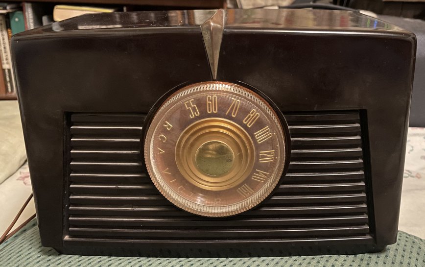
I have this "All American 6ix" tube radio circuit board I decided to install inside an RCA cabinet. It had been working quite well, and decided it needed a good home inside a nice radio cabinet. |
|
|
Return to top of page · Post #: 2 · Written at 9:43:47 AM on 17 July 2025.
|
|
|
|
Location: Oradell, US
Member since 2 April 2010 Member #: 643 Postcount: 835 |
|
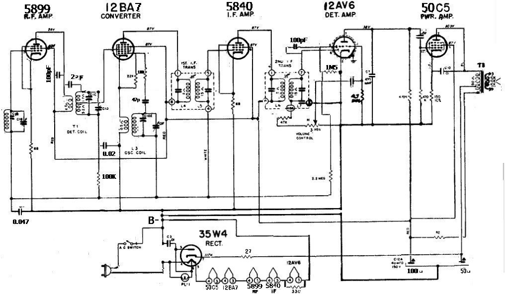
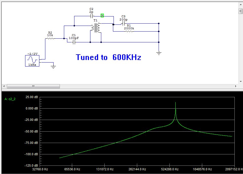
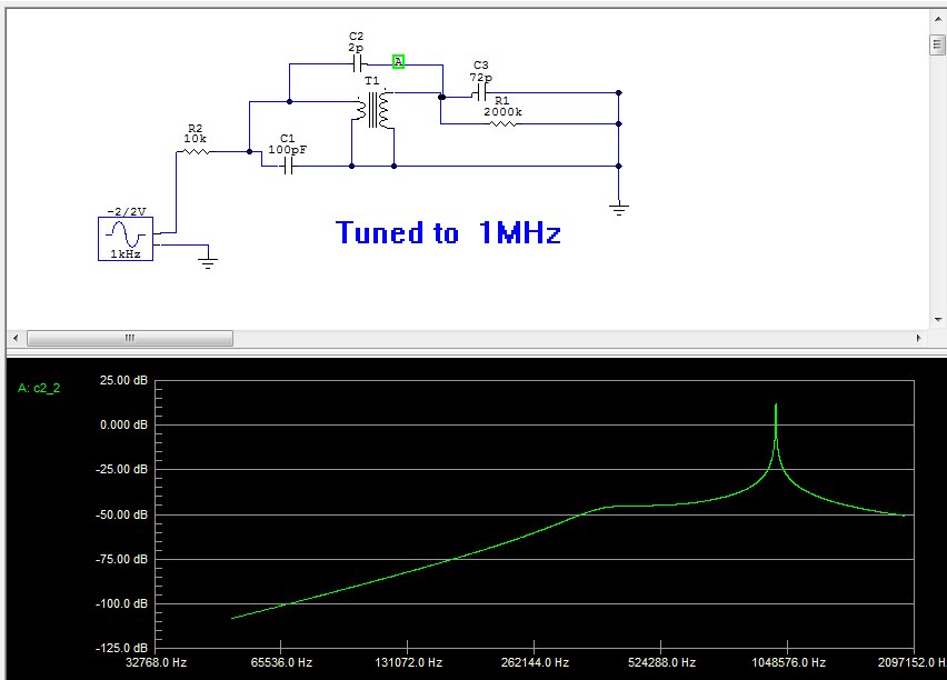
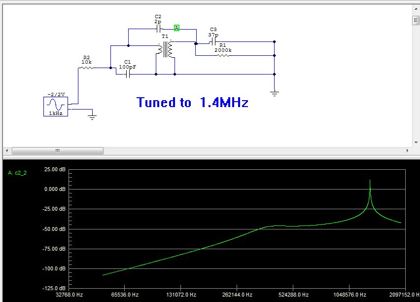
This above radio has an RF amp stage and 3 gang tuning cap. the RF amp tube feeds an RF transformer T1 that has a fixed cap C1 (in the simulation schematic) across the primary, and the secondary has the 2nd tuning cap C3 on it. The primary L measures 1700uH and with the 100pF cap it would resonate at 386kHz. The secondary L forms an LC circuit with the 2nd tuning cap. As you can see in the schematic in my above first post. Seems a strange circuit, so I did simulations of this. The secondary LC circuit dominates, and produces a tunable resonance. The resonant peaks are about the same amplitude. |
|
|
« Back ·
1 ·
Next »
|
|
|
You need to be a member to post comments on this forum.
|
|

Sign In
Vintage Radio and Television is proudly brought to you by an era where things were built with pride and made to last.
DISCLAIMER: Valve radios and televisions contain voltages that can deliver lethal shocks. You should not attempt to work on a valve radio or other electrical appliances unless you know exactly what you are doing and have gained some experience with electronics and working around high voltages. The owner, administrators and staff of Vintage Radio & Television will accept no liability for any damage, injury or loss of life that comes as a result of your use or mis-use of information on this website. Please read our Safety Warning before using this website.
WARNING: Under no circumstances should you ever apply power to a vintage radio, television or other electrical appliance you have acquired without first having it checked and serviced by an experienced person. Also, at no time should any appliance be connected to an electricity supply if the power cord is damaged. If in doubt, do not apply power.
Shintara - Keepin' It Real · VileSilencer - Maintain The Rage