Tech Talk
Forum home - Go back to Tech talk
|
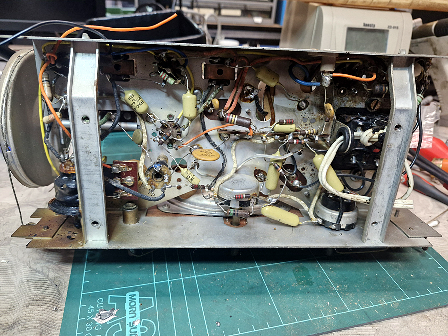
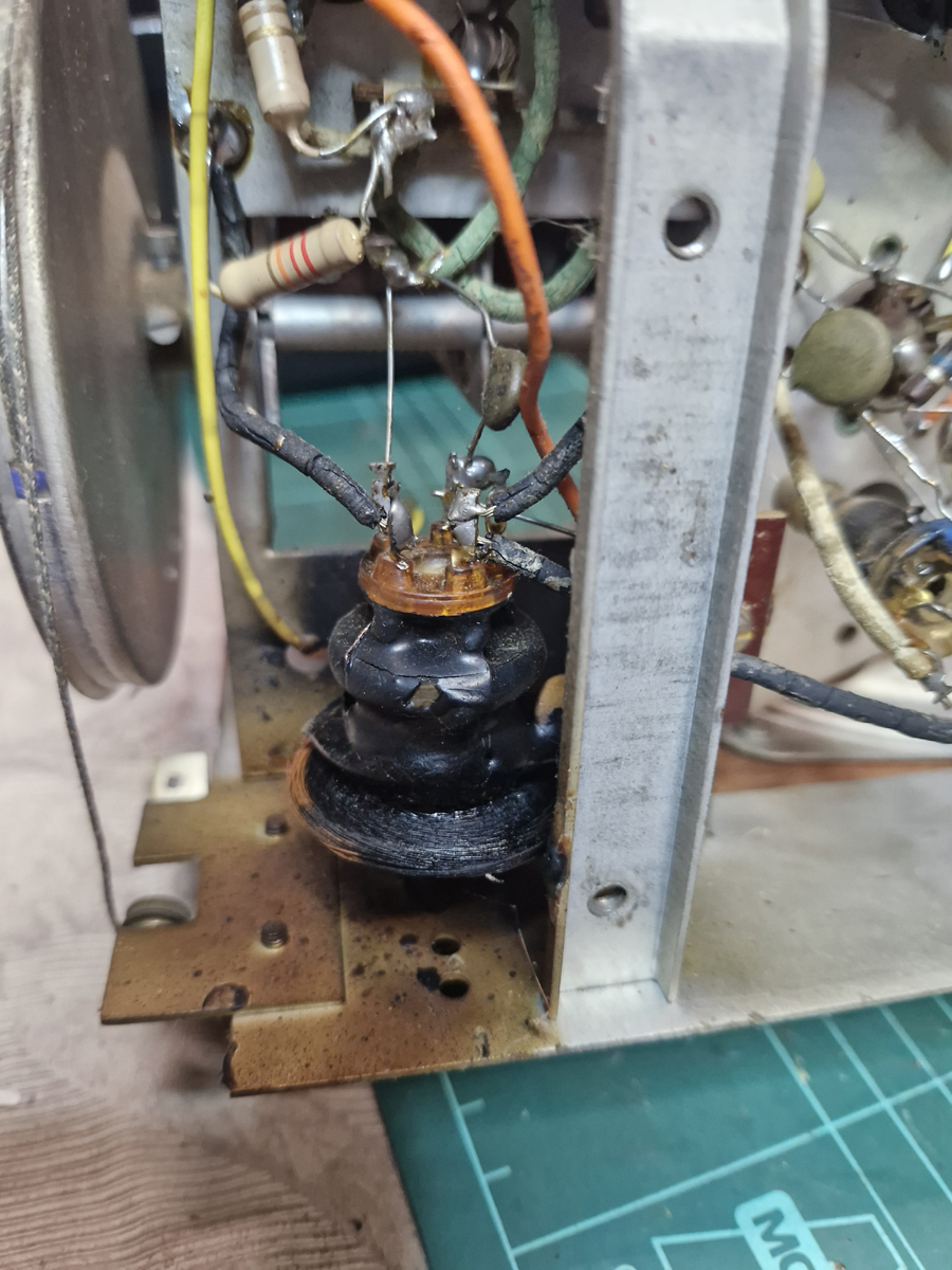
Im Back.... with a Fried AWA Antenna Coil
|
|
|
Return to top of page · Post #: 1 · Written at 3:39:37 PM on 20 August 2024.
|
|
|
|
Location: Adelaide, SA
Member since 27 February 2010 Member #: 630 Postcount: 398 |
|
Hi All   ‾‾‾‾‾‾‾‾‾‾‾‾‾‾‾‾‾‾‾‾‾‾‾‾‾‾‾‾‾‾‾‾‾‾‾‾‾‾‾‾‾‾‾‾‾‾‾‾‾‾‾‾‾‾‾‾‾‾‾‾‾‾‾‾‾‾‾‾ Valve radios, They just don't make them like they used to |
|
|
Return to top of page · Post #: 2 · Written at 8:21:47 PM on 20 August 2024.
|
|
|
|
Administrator
Location: Naremburn, NSW
Member since 15 November 2005 Member #: 1 Postcount: 7595 |
|
Welcome back, Flakes. It has indeed been a long time. ‾‾‾‾‾‾‾‾‾‾‾‾‾‾‾‾‾‾‾‾‾‾‾‾‾‾‾‾‾‾‾‾‾‾‾‾‾‾‾‾‾‾‾‾‾‾‾‾‾‾‾‾‾‾‾‾‾‾‾‾‾‾‾‾‾‾‾‾ A valve a day keeps the transistor away... |
|
|
Return to top of page · Post #: 3 · Written at 9:11:06 PM on 20 August 2024.
|
|
|
|
Location: Hill Top, NSW
Member since 18 September 2015 Member #: 1801 Postcount: 2233 |
|
Looks like one photo was included twice. |
|
|
Return to top of page · Post #: 4 · Written at 12:00:58 AM on 21 August 2024.
|
|
|
|
Administrator
Location: Naremburn, NSW
Member since 15 November 2005 Member #: 1 Postcount: 7595 |
|
Good pickup - all fixed now. ‾‾‾‾‾‾‾‾‾‾‾‾‾‾‾‾‾‾‾‾‾‾‾‾‾‾‾‾‾‾‾‾‾‾‾‾‾‾‾‾‾‾‾‾‾‾‾‾‾‾‾‾‾‾‾‾‾‾‾‾‾‾‾‾‾‾‾‾ A valve a day keeps the transistor away... |
|
|
Return to top of page · Post #: 5 · Written at 8:36:07 AM on 21 August 2024.
|
|
|
|
Location: NSW
Member since 10 June 2010 Member #: 681 Postcount: 1391 |
|
Is it reallly fried? It looks to have been encapsulated in black wax, but there are no signs of burning. But maybe your nose tells you. How is the continuity? |
|
|
Return to top of page · Post #: 6 · Written at 1:08:26 PM on 21 August 2024.
|
|
|
|
Location: Melbourne, VIC
Member since 20 September 2011 Member #: 1009 Postcount: 1261 |
|
The aerial coil part number is 30768 and was used in many AWA models. |
|
|
Return to top of page · Post #: 7 · Written at 2:06:16 PM on 21 August 2024.
|
|
|
|
Location: Adelaide, SA
Member since 27 February 2010 Member #: 630 Postcount: 398 |
|
Yes its totally fried. have a close look at the bottom part of the coil its copper and burnt black. Also look at the chassis and its a brown burnt colour with splatter of black wax/tar. ‾‾‾‾‾‾‾‾‾‾‾‾‾‾‾‾‾‾‾‾‾‾‾‾‾‾‾‾‾‾‾‾‾‾‾‾‾‾‾‾‾‾‾‾‾‾‾‾‾‾‾‾‾‾‾‾‾‾‾‾‾‾‾‾‾‾‾‾ Valve radios, They just don't make them like they used to |
|
|
Return to top of page · Post #: 8 · Written at 3:56:43 PM on 21 August 2024.
|
|
|
|
Location: Sydney, NSW
Member since 28 January 2011 Member #: 823 Postcount: 6914 |
|
Yes its totally fried. have a close look at the bottom part of the coil its copper and burnt black. |
|
|
Return to top of page · Post #: 9 · Written at 3:59:50 PM on 21 August 2024.
|
|
|
|
Location: Wangaratta, VIC
Member since 21 February 2009 Member #: 438 Postcount: 5671 |
|
If this is cooked, rather than the tar fall off that is bizarre. If it is the primary winding the only thing that can burn it out in normal operation is lightning. There are no circuits hooked to it that could do that unless it got hit by lightning and that's rare. But I have had two and that only wiped out caps & resistors. |
|
|
Return to top of page · Post #: 10 · Written at 6:01:43 PM on 21 August 2024.
|
|
|
|
Location: Hill Top, NSW
Member since 18 September 2015 Member #: 1801 Postcount: 2233 |
|
I agree, the situation is quite bizarre. I'd like to see resistance readings on each winding, as well as from one to the other, before condemning it. |
|
|
Return to top of page · Post #: 11 · Written at 7:29:10 PM on 21 August 2024.
|
|
|
|
Location: Adelaide, SA
Member since 27 February 2010 Member #: 630 Postcount: 398 |
|
Hi Guys ‾‾‾‾‾‾‾‾‾‾‾‾‾‾‾‾‾‾‾‾‾‾‾‾‾‾‾‾‾‾‾‾‾‾‾‾‾‾‾‾‾‾‾‾‾‾‾‾‾‾‾‾‾‾‾‾‾‾‾‾‾‾‾‾‾‾‾‾ Valve radios, They just don't make them like they used to |
|
|
Return to top of page · Post #: 12 · Written at 8:07:40 PM on 21 August 2024.
|
|
|
|
Location: Belrose, NSW
Member since 31 December 2015 Member #: 1844 Postcount: 2680 |
|
I have an AWA WW2 vintage Army Amenities receiver that runs on 6 volts. |
|
|
Return to top of page · Post #: 13 · Written at 8:55:30 PM on 21 August 2024.
|
|
|
|
Location: Toongabbie, NSW
Member since 19 November 2015 Member #: 1828 Postcount: 1394 |
|
I know this is bizarre BUT. |
|
|
Return to top of page · Post #: 14 · Written at 1:50:35 PM on 22 August 2024.
|
|
|
|
Location: Cameron Park, NSW
Member since 5 November 2010 Member #: 770 Postcount: 426 |
|
AWA did use a capacitor from the mains input to the antenna terminal as an internal antenna, an example is the model 520M. |
|
|
Return to top of page · Post #: 15 · Written at 3:48:06 PM on 22 August 2024.
|
|
|
|
Location: Wangaratta, VIC
Member since 21 February 2009 Member #: 438 Postcount: 5671 |
|
Interesting. Got half way through the post & the internet died & the site would not reload? |
|
|
You need to be a member to post comments on this forum.
|
|

Sign In

Vintage Radio and Television is proudly brought to you by an era where things were built with pride and made to last.
DISCLAIMER: Valve radios and televisions contain voltages that can deliver lethal shocks. You should not attempt to work on a valve radio or other electrical appliances unless you know exactly what you are doing and have gained some experience with electronics and working around high voltages. The owner, administrators and staff of Vintage Radio & Television will accept no liability for any damage, injury or loss of life that comes as a result of your use or mis-use of information on this website. Please read our Safety Warning before using this website.
WARNING: Under no circumstances should you ever apply power to a vintage radio, television or other electrical appliance you have acquired without first having it checked and serviced by an experienced person. Also, at no time should any appliance be connected to an electricity supply if the power cord is damaged. If in doubt, do not apply power.
Shintara - Keepin' It Real · VileSilencer - Maintain The Rage

