
Tech Talk
Forum home - Go back to Tech talk
|
Astor Mickey
|
|
|
Return to top of page · Post #: 1 · Written at 6:42:13 PM on 30 July 2024.
|
|
|
|
Location: Nowra, NSW
Member since 19 February 2023 Member #: 2539 Postcount: 19 |
|
Owner wants me to fix this one. Being a novice, I have had a good look at it, and commenced carefully cleaning it up. Interesting that it has an ECH34 valve (frequency converter?). Any thoughts welcome before I carefully take the plunge. 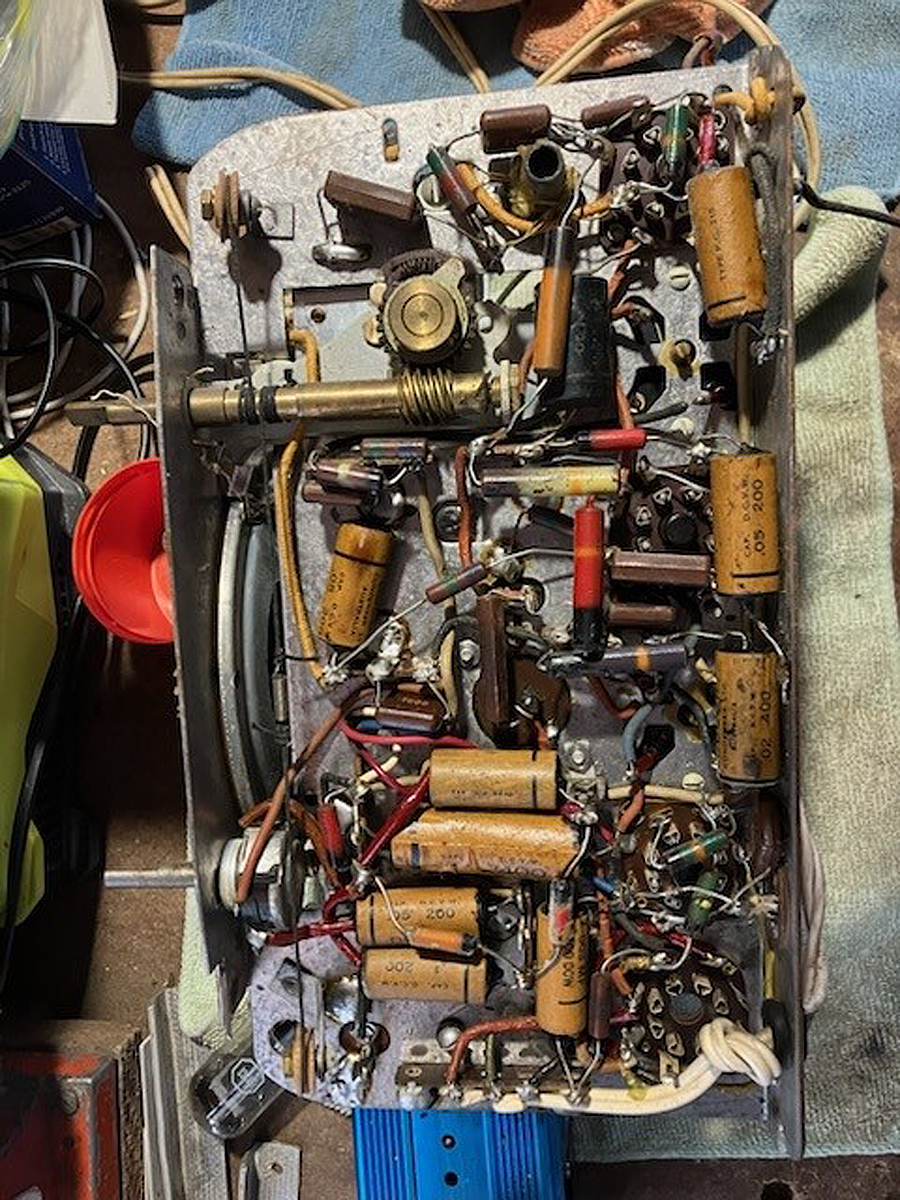 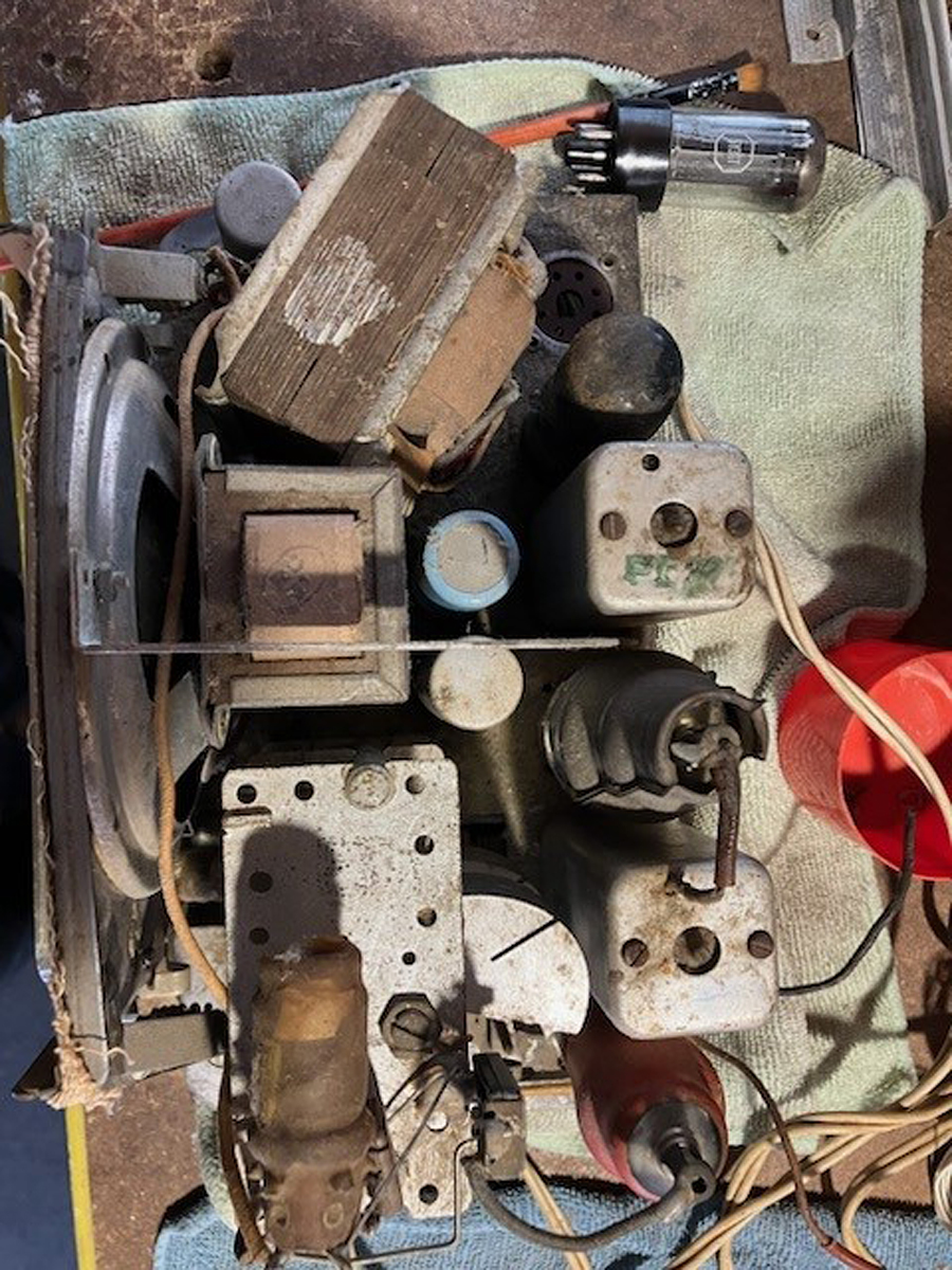 |
|
|
Return to top of page · Post #: 2 · Written at 10:03:04 PM on 30 July 2024.
|
|

|
Location: Wangaratta, VIC
Member since 21 February 2009 Member #: 438 Postcount: 5733 |
|
One: Find the model number, that will lead you/ us to the circuit. |
|
|
Return to top of page · Post #: 3 · Written at 6:04:06 PM on 31 July 2024.
|
|
|
|
Location: Nowra, NSW
Member since 19 February 2023 Member #: 2539 Postcount: 19 |
|
Thanks for the interest Marcc. |
|
|
Return to top of page · Post #: 4 · Written at 8:31:24 PM on 31 July 2024.
|
|
|
|
Location: Wangaratta, VIC
Member since 21 February 2009 Member #: 438 Postcount: 5733 |
|
KM is the model: year 1947 |
|
|
Return to top of page · Post #: 5 · Written at 8:55:06 PM on 31 July 2024.
|
|
|
|
Location: Toongabbie, NSW
Member since 19 November 2015 Member #: 1828 Postcount: 1414 |
|
Hi Wodbore, have a look at my post in the special projects section 'An Astor Mickey to restore'. |
|
|
Return to top of page · Post #: 6 · Written at 10:09:27 PM on 31 July 2024.
|
|
|
|
Location: Wangaratta, VIC
Member since 21 February 2009 Member #: 438 Postcount: 5733 |
|
Full data sheet: https://www.kevinchant.com/uploads/7/1/0/8/7108231/kl.pdf |
|
|
Return to top of page · Post #: 7 · Written at 10:43:51 PM on 31 July 2024.
|
|

|
Administrator
Location: Naremburn, NSW
Member since 15 November 2005 Member #: 1 Postcount: 7643 |
|
Photos uploaded. ‾‾‾‾‾‾‾‾‾‾‾‾‾‾‾‾‾‾‾‾‾‾‾‾‾‾‾‾‾‾‾‾‾‾‾‾‾‾‾‾‾‾‾‾‾‾‾‾‾‾‾‾‾‾‾‾‾‾‾‾‾‾‾‾‾‾‾‾ A valve a day keeps the transistor away... |
|
|
Return to top of page · Post #: 8 · Written at 12:06:38 AM on 1 August 2024.
|
|

|
Location: Hill Top, NSW
Member since 18 September 2015 Member #: 1801 Postcount: 2264 |
|
Thanks for uploading the photos. |
|
|
Return to top of page · Post #: 9 · Written at 1:13:17 AM on 1 August 2024.
|
|

|
Location: Melbourne, VIC
Member since 20 September 2011 Member #: 1009 Postcount: 1267 |
|
There is a version of the Astor KM with a ECH34 valve. |
|
|
Return to top of page · Post #: 10 · Written at 7:18:30 AM on 1 August 2024.
|
|
|
|
Location: Toongabbie, NSW
Member since 19 November 2015 Member #: 1828 Postcount: 1414 |
|
Just looked at photos in post #1. |
|
|
Return to top of page · Post #: 11 · Written at 10:34:54 AM on 1 August 2024.
|
|
|
|
Location: Wangaratta, VIC
Member since 21 February 2009 Member #: 438 Postcount: 5733 |
|
You can download the info from radio museum and compare the wiring of the frequency changer. To ensure it matches the tube. Check the ECH 34 for loose base as that can indicate a breakage of the connection to the metallisation as noted. |
|
|
Return to top of page · Post #: 12 · Written at 10:40:53 AM on 1 August 2024.
|
|
|
|
Location: Wangaratta, VIC
Member since 21 February 2009 Member #: 438 Postcount: 5733 |
|
Note 50K and 500K resistors of that era, have an attrition rate, along with plate resistors on detector first audio (6B8). Grid resistors on 6V6 (and many output tubes) never leave unchecked. |
|
|
Return to top of page · Post #: 13 · Written at 6:32:18 PM on 3 August 2024.
|
|
|
|
Location: Nowra, NSW
Member since 19 February 2023 Member #: 2539 Postcount: 19 |
|
Wow. Thank you guys for all the advice - it will take some time to digest. |
|
|
Return to top of page · Post #: 14 · Written at 9:00:17 AM on 4 August 2024.
|
|
|
|
Location: Belrose, NSW
Member since 31 December 2015 Member #: 1844 Postcount: 2714 |
|
There is a wax paper cap that looks like it's across the B+. It has been getting hot, so it has to go prior to any powering attempts, along with all the other wax papers later in the process. |
|
|
Return to top of page · Post #: 15 · Written at 10:24:50 AM on 4 August 2024.
|
|
|
|
Location: Wangaratta, VIC
Member since 21 February 2009 Member #: 438 Postcount: 5733 |
|
That big black cap with a band on it is also paper and a type that cracks its jacket & shorts. The two brown resistors should be checked albeit they often look overheated. In overload the one from CT to ground (back bias) can burn. do not increase its wattage: Better it burns than the transformer. |
|
|
You need to be a member to post comments on this forum.
|
|
Sign In
Vintage Radio and Television is proudly brought to you by an era where things were built with pride and made to last.
DISCLAIMER: Valve radios and televisions contain voltages that can deliver lethal shocks. You should not attempt to work on a valve radio or other electrical appliances unless you know exactly what you are doing and have gained some experience with electronics and working around high voltages. The owner, administrators and staff of Vintage Radio & Television will accept no liability for any damage, injury or loss of life that comes as a result of your use or mis-use of information on this website. Please read our Safety Warning before using this website.
WARNING: Under no circumstances should you ever apply power to a vintage radio, television or other electrical appliance you have acquired without first having it checked and serviced by an experienced person. Also, at no time should any appliance be connected to an electricity supply if the power cord is damaged. If in doubt, do not apply power.
Shintara - Keepin' It Real · VileSilencer - Maintain The Rage