Welcome to Australia's only Vintage Radio and Television discussion forums. You are not logged in. Please log in below, apply for an account or retrieve your password.
Australian Vintage Radio Forums
  Home  ·  About Us  ·  Discussion Forums  ·  Glossary  ·  Outside Links  ·  Policies  ·  Services Directory  ·  Safety Warnings  ·  Tutorials

Tech Talk

Forum home - Go back to Tech talk

 Four valve neutrodyne
« Back · 1 · 2 · Next »
 Return to top of page · Post #: 1 · Written at 3:04:43 PM on 31 May 2023.
Simplex's Gravatar
 Location: Bathurst, NSW
 Member since 7 August 2008
 Member #: 336
 Postcount: 391

Recently I acquired a homebrew neutrodyne set. Valves A415 RF Amp, 172B Detector, 172B 1st Audio, A415 Audio o/p. At least that is the valve lineup as found.

Traced out the wiring as did not have a circuit diagram.

There are two Signal brand interstage coupling transformers. The secondaries marked F -ve are linked by a busbar and from one of the terminal posts there is a strange wander lead. As found this wander lead was connected to the aerial terminal of the RF Amp stage. This is incorrect and just killed the radio.
However found that putting this wander lead onto the ground terminal the set starts working. Not brilliantly but enough to hear stations here and there.

So next tried some negative grid bias. Put a couple of AA cells (3 v) in a battery holder, put the positive onto GRND post and put the -ve onto the linked transformer F -ve post.

The set comes to life, plenty of audio from the speaker but a little bit of distortion. Actually quite a lively set once the controls are worked out.
(Still some adjusting of the neutrallising cap to be done.)

Still trying to work out what is correct and comments welcome.

Notice that the tuned circuit of the RF Amp is connected to the battery -ve rail.

However the rotor of the Detector tuneing capacitor goes to the battery +ve rail. And the GRND post (earth) is also connected to the +ve rail.

Would have thought these should be on the -ve rail.

The 1μF bypass capacitor also goes to the +ve rail. Would have thought it should go to the -ve rail. There are a few things to be cleared up.

Does anyone have a circuit of this set which may clarify things. A circuit would be great help.

Any comments on the above questions would be appreciated.

EDIT: Stumbled across a similar circuit which shows the 1st aerial tank (RF Amp) and the earth post going to A -ve while the next tuneing tank for the detector is connected to the A +ve rail.

So will try connecting the earth post to the A -ve rail and see what transpires.

Unknown valve radio
Unknown valve radio

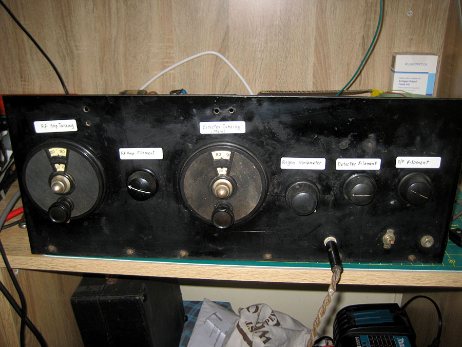
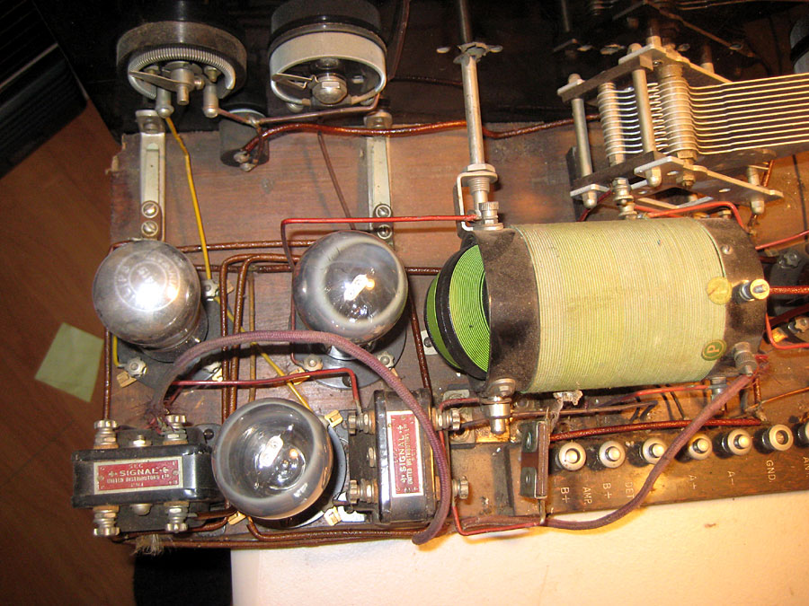
Circuit diagram for this radio


 Return to top of page · Post #: 2 · Written at 9:39:35 PM on 31 May 2023.
Marcc's avatar
 Location: Wangaratta, VIC
 Member since 21 February 2009
 Member #: 438
 Postcount: 5257

Those things look simple, but they are not.

It would be pertinent to draw a circuit. Those are, I would expect, only Triodes where the big pins are filaments and the rest a trap if they're top wired. The tube doing the detecting may not get bias depending on how many plate volts are on it?

The plates will always get positive and the grids mainly from a small battery: Negative. There may be a filament battery. Negative is normally on the rheostat. Some tubes have a preferred polarity on the filament pins.

The filaments are part of the tube bias and the one for the detector often has a preferred side of the filament.

Tube data franks electron tube pages. If it's not neutralised properly, it will oscillate.

Marc


 Return to top of page · Post #: 3 · Written at 7:35:59 AM on 1 June 2023.
Simplex's Gravatar
 Location: Bathurst, NSW
 Member since 7 August 2008
 Member #: 336
 Postcount: 391

Have drawn a circuit and sent it off for processing.

Noted the comments about the polarity of the filaments. The valve bases have the filament polarity clearly marked on them. Yet the constructor has for some reason done all the filament wiring back to front.

A terminal strip with binding posts and +ve / -ve engraved on it. So for the moment will just reverse the battery polarity and see how things go.

Lot of work went into this set, all wiring done neatly with square busbar. Good quality components and sound construction practices. So why the filaments are so wired is a mystery.

EDIT: Transposing polarity a failure, just howls. So restored to the way it was and working quite well.

Listening to 2CR 549kHz with excellent loudspeaker strength. Bellowing if the volume is turned up and get the impression this is quite a lively set.

Have heard 2EL (Orange) very strong and 2LT quite strong.

The aerial only about 10 metres of wire draped along a fence.

Have the 3V -ve bias battery in circuit and this seems to work well.

One boo boo with the circuit diagram when it appears.....both audio valves filaments are tied to the one rheostat.


 Return to top of page · Post #: 4 · Written at 10:03:06 AM on 1 June 2023.
Marcc's avatar
 Location: Wangaratta, VIC
 Member since 21 February 2009
 Member #: 438
 Postcount: 5257

The rheostat is the volume control. A415 at 150V plate need-4.5V on the grid. If there is too much radiation and poor neutralisation & too much gain, or regeneration, that's when they oscillate.


 Return to top of page · Post #: 5 · Written at 10:32:57 AM on 1 June 2023.
Simplex's Gravatar
 Location: Bathurst, NSW
 Member since 7 August 2008
 Member #: 336
 Postcount: 391

Yes the last rheostat is the volume control although so loud is the signal have to reduce the rheostat for the RF amp valve a bit.

My H.T battery bank only supplies 90v max which seems ok for now. Shall make up a -4.5v bias battery, this appears to be the better bias voltage from some of the circuits that are about.

Still at a loss as to why the builder of this set whom took such care with a high standard of workmanship , clearly was knowledgeable had a wander lead crudely attached to the coupling transformer and then draped about the set.

Plus the lack of -ve grid bias. From looking at the neutrodyne circuits of that era nearly all of them have a grid bias battery for the audio stages.

Have adjusted the neutralising capacitor, this appears to be sorted out.

The set is going well with what has been done so far. Just a few things to be tidyed up.

Unfortunately I am going away for a few weeks so shall leave the set as is for now.

Thanks for all the comments and will pick up this thread again when I return.


 Return to top of page · Post #: 6 · Written at 11:07:59 AM on 1 June 2023.
Robbbert's avatar
 Location: Hill Top, NSW
 Member since 18 September 2015
 Member #: 1801
 Postcount: 2017

Sounds like you've picked up a good radio.

Those 3 stations (2CR, 2LT, 2EL) are all audible in Sydney during the day, so I'm wondering if you can pick up any Sydney stations? 2FC and 2BL would be the obvious ones.


 Return to top of page · Post #: 7 · Written at 5:10:34 PM on 1 June 2023.
Simplex's Gravatar
 Location: Bathurst, NSW
 Member since 7 August 2008
 Member #: 336
 Postcount: 391

Alas have had to put the project aside as soon to be away for a couple of weeks. Upon my return will finish tyding up things such as the grid bias and a couple of other matters.

That done will try some DX listening.

Thanks for your interest.


 Return to top of page · Post #: 8 · Written at 8:13:00 PM on 5 June 2023.
Brad's avatar
 Administrator
 Location: Naremburn, NSW
 Member since 15 November 2005
 Member #: 1
 Postcount: 7304

Photos and document uploaded.

My apologies for the late response. I have been away for a few days.


‾‾‾‾‾‾‾‾‾‾‾‾‾‾‾‾‾‾‾‾‾‾‾‾‾‾‾‾‾‾‾‾‾‾‾‾‾‾‾‾‾‾‾‾‾‾‾‾‾‾‾‾‾‾‾‾‾‾‾‾‾‾‾‾‾‾‾‾
A valve a day keeps the transistor away...

 
 Return to top of page · Post #: 9 · Written at 8:29:43 PM on 5 June 2023.
Marcc's avatar
 Location: Wangaratta, VIC
 Member since 21 February 2009
 Member #: 438
 Postcount: 5257

One of the first wires to clean up is that cloth one. In the ideal world, wires should cross at 90 degrees.

If you have a a regulated solid state psu decoupling can be an issue & electrolytics under47μF are ineffective. and a cap of 0.1μF placed across B+ to improve decoupling. I like having "A", "B" & "C" coming off of different secondaries.

Due to the way some mains grids are wired it is unwise to directly ground the set. That sends some power supplies crazy. Ground only via a 0.01 μF approved line cap.


 Return to top of page · Post #: 10 · Written at 7:17:44 AM on 8 June 2023.
Simplex's Gravatar
 Location: Bathurst, NSW
 Member since 7 August 2008
 Member #: 336
 Postcount: 391

Thanks Brad for putting the photos in. Did the circuit diagram one get through ?

Am out in the bush and away from the radio.

Yes the cloth wire was the odd wander lead which went to the receiver front end as earlier mentioned. Now temporily connected to a grid bias battery which has really improved things. Will tydie that up upon my return and install a bias battery holder.

Noted the comments about decoupling on a solid state power supply. There is a little bit of hum so will attend to this when I get back home.

On earthing found the problem mentioned so put a 1:1 isolating transformer for the power supply which solved that problem.

H.T comes from a battery bank of AAA cells as sometimes take my regen sets out on camping trips. Alkalines last a long time.

Thanks for the comments so far.


 Return to top of page · Post #: 11 · Written at 9:07:34 AM on 8 June 2023.
Robbbert's avatar
 Location: Hill Top, NSW
 Member since 18 September 2015
 Member #: 1801
 Postcount: 2017

Did the circuit diagram one get through ?

It did, looks quite a simple circuit. Only 3 fixed capacitors and 1 fixed resistor.


 Return to top of page · Post #: 12 · Written at 10:55:08 AM on 8 June 2023.
Marcc's avatar
 Location: Wangaratta, VIC
 Member since 21 February 2009
 Member #: 438
 Postcount: 5257

A commercial battery holder can be adapted for bias. Beware: If using a 7905 or similar for bias; Grids draw infinitely small current. So a loading resistor for 5mA will be needed, or it won't regulate.

A normal transformer where there is no contact between primary & secondary, is isolating. Do note the strategic placement of diodes. The back EMF from caps & transformers can destroy transistors & regulators. I do tend to use LR8 for low current HV. You can use them for 45V and say 135V off of the same supply rail. Loading resistor applies, of which its voltage divider is part.

Electrolytic caps are not the best for decoupling RF. That is why you need a non polarised cap of around 0.047 to 0.22μF across the supply (Ecap).

Marc


 Return to top of page · Post #: 13 · Written at 3:12:26 PM on 6 July 2023.
Simplex's Gravatar
 Location: Bathurst, NSW
 Member since 7 August 2008
 Member #: 336
 Postcount: 391

After having been away for a few weeks recommenced work on this set. After a lot of experimentation found a bias of -ve 3 volts for the grids of the two audio valves is best.

This is with 90v on the H.T which is as much as my battery bank supplies. Do not have a mains supplied H.T supply as yet. One day will make one.


 Return to top of page · Post #: 14 · Written at 10:21:55 AM on 8 July 2023.
Marcc's avatar
 Location: Wangaratta, VIC
 Member since 21 February 2009
 Member #: 438
 Postcount: 5257

With battery sets like that I have a still to be electrically overhauled Philips 3003 unit from the 1920's. Its on Radio Museum.

However, the Philips tubes tended to be 4V but some were 6V as that tied in nicely with Lead Acid Batteries. Fuse is recommended.

Normally here, even that there is a PSU that will handle it, the object is to go and get some duct tape and a bunch of "el cheapo" 6LR61-9V batteries. and a connector Jaycar PH9230.

The batteries will link into one another one up one down; Ten make 90V; Five make 45V; Fifteen make 135V; and you will be amazed at how long they last.

You cut PH 9230 in half to make the battery connectors and the duck tape stops them (and other things,) quacking apart. during the experimental stage of getting it going.


 Return to top of page · Post #: 15 · Written at 1:28:29 PM on 9 July 2023.
Simplex's Gravatar
 Location: Bathurst, NSW
 Member since 7 August 2008
 Member #: 336
 Postcount: 391

Have made up a H.T battery bank with AAA cells, plenty of capacity. This battery bank is used with other radios as well.

Running the filaments of a mains supply but will soon have a four volt SLA battery bank made up.

Intend to take this set out on a camping trips so hence the batteries.


« Back · 1 · 2 · Next »
 You need to be a member to post comments on this forum.

Sign In

Username:
Password:
 Keep me logged in.
Do not tick box on a computer with public access.