
Tech Talk
Forum home - Go back to Tech talk
|
AWA Longwave transmitter inductance coil with 12 taps and central rotatable coil segment from circa 1930-40's
|
|
|
« Back ·
1 ·
Next »
|
|
|
Return to top of page · Post #: 1 · Written at 12:02:37 PM on 21 March 2022.
|
|
|
|
Location: Melbourne, VIC
Member since 11 July 2012 Member #: 1179 Postcount: 65 |
|
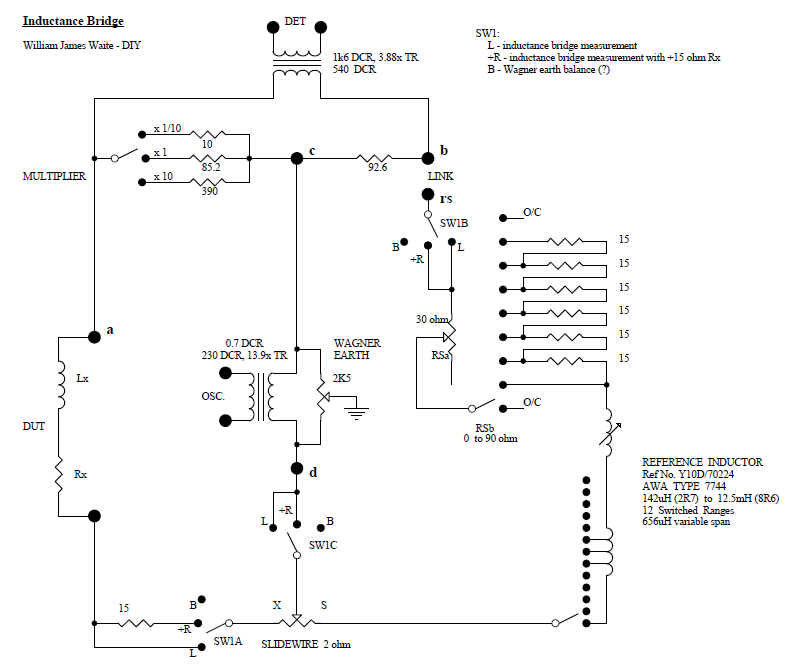
I have a Type 7744 inductor assembly with markings Ref No. Y10D/70224. It is the same assembly as shown in the Powerhouse museum collection - link to photo https://api.maas.museum/object/263493 -, and identified as an AWA Longwave transmitter inductance coil from circa 1938. |
|
|
Return to top of page · Post #: 2 · Written at 5:19:35 PM on 24 March 2022.
|
|
|
|
Location: Melbourne, VIC
Member since 11 July 2012 Member #: 1179 Postcount: 65 |
|
I was able to measure the tapped/variable inductor and it has a span from 142uH to 12.5mH. The variable portion is from zero to 656uH, and the taps are mainly 1 to 1.3mH steps (so not accurately 1.0mH steps). |
|
|
Return to top of page · Post #: 3 · Written at 3:33:06 PM on 25 March 2022.
|
|
|
|
Location: Melbourne, VIC
Member since 11 July 2012 Member #: 1179 Postcount: 65 |
|
Just identified that this coil was originally part of the RAAF's AT5 M/F aircraft communication installation's Aerial Coupling Unit that was made by AWA in large numbers for WW2 (photos and manual on-line). The manual only identifies the coil is made from litz wire, with no inductance values. |
|
|
Return to top of page · Post #: 4 · Written at 9:29:24 PM on 25 March 2022.
|
|
|
|
Location: Linton, VIC
Member since 30 December 2016 Member #: 2028 Postcount: 472 |
|
That is one heck of an impressive coil Trobbins. |
|
|
Return to top of page · Post #: 5 · Written at 8:50:03 AM on 26 March 2022.
|
|
|
|
Location: Melbourne, VIC
Member since 11 July 2012 Member #: 1179 Postcount: 65 |
|
Photos of the AT5 installation are in following link. The Aerial Coupling Unit was an enclosed chassis. |
|
|
« Back ·
1 ·
Next »
|
|
|
You need to be a member to post comments on this forum.
|
|
Sign In
Vintage Radio and Television is proudly brought to you by an era where things were built with pride and made to last.
DISCLAIMER: Valve radios and televisions contain voltages that can deliver lethal shocks. You should not attempt to work on a valve radio or other electrical appliances unless you know exactly what you are doing and have gained some experience with electronics and working around high voltages. The owner, administrators and staff of Vintage Radio & Television will accept no liability for any damage, injury or loss of life that comes as a result of your use or mis-use of information on this website. Please read our Safety Warning before using this website.
WARNING: Under no circumstances should you ever apply power to a vintage radio, television or other electrical appliance you have acquired without first having it checked and serviced by an experienced person. Also, at no time should any appliance be connected to an electricity supply if the power cord is damaged. If in doubt, do not apply power.
Shintara - Keepin' It Real · VileSilencer - Maintain The Rage