
Tech Talk
Forum home - Go back to Tech talk
|
Electrosound Radiogram
|
|
|
« Back ·
1 ·
Next »
|
|
|
Return to top of page · Post #: 1 · Written at 8:28:00 PM on 16 October 2021.
|
|
|
|
Location: Perth, WA
Member since 7 May 2012 Member #: 1140 Postcount: 157 |
|
Hello folks, 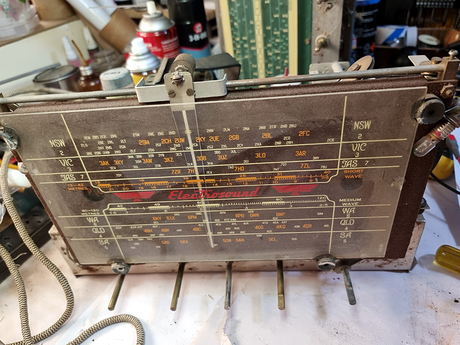 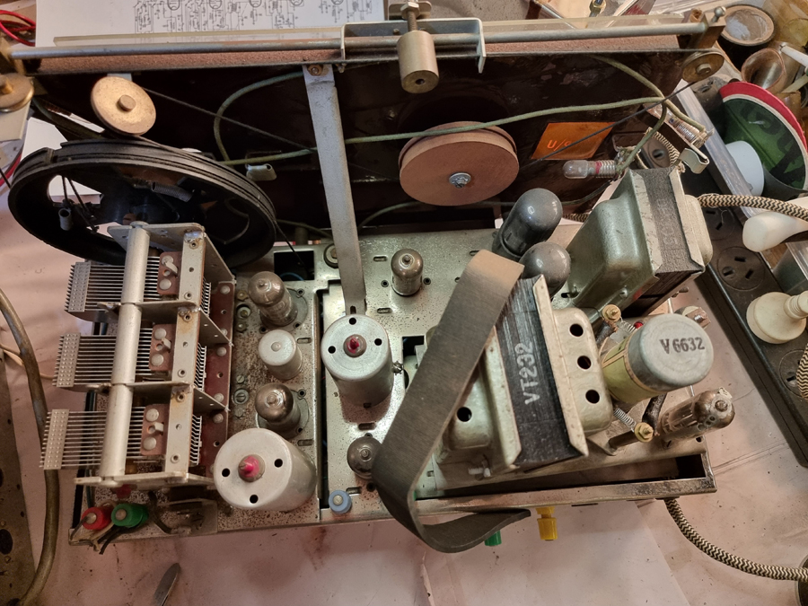 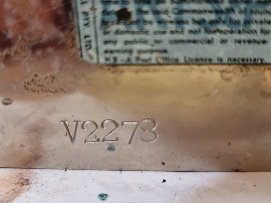 |
|
|
Return to top of page · Post #: 2 · Written at 8:43:48 PM on 16 October 2021.
|
|

|
Location: Wangaratta, VIC
Member since 21 February 2009 Member #: 438 Postcount: 5715 |
|
Be careful of the interpretation of running on 240V. Several chasses like that had a modular set up where the Vibrator PSU was removed & the mains one put in its place. |
|
|
Return to top of page · Post #: 3 · Written at 10:01:07 PM on 16 October 2021.
|
|

|
Location: Sydney, NSW
Member since 28 January 2011 Member #: 823 Postcount: 6949 |
|
What is the valve line-up for the particular chassis that you seek a schematic for? |
|
|
Return to top of page · Post #: 4 · Written at 3:50:50 PM on 17 October 2021.
|
|
|
|
Location: Perth, WA
Member since 7 May 2012 Member #: 1140 Postcount: 157 |
|
What is the valve line-up for the particular chassis that you seek a schematic for? |
|
|
Return to top of page · Post #: 5 · Written at 3:52:10 PM on 17 October 2021.
|
|
|
|
Location: Perth, WA
Member since 7 May 2012 Member #: 1140 Postcount: 157 |
|
Hi Marcc, |
|
|
Return to top of page · Post #: 6 · Written at 10:03:23 PM on 17 October 2021.
|
|

|
Administrator
Location: Naremburn, NSW
Member since 15 November 2005 Member #: 1 Postcount: 7624 |
|
Photos uploaded. ‾‾‾‾‾‾‾‾‾‾‾‾‾‾‾‾‾‾‾‾‾‾‾‾‾‾‾‾‾‾‾‾‾‾‾‾‾‾‾‾‾‾‾‾‾‾‾‾‾‾‾‾‾‾‾‾‾‾‾‾‾‾‾‾‾‾‾‾ A valve a day keeps the transistor away... |
|
|
Return to top of page · Post #: 7 · Written at 12:37:28 AM on 18 October 2021.
|
|

|
Location: Hill Top, NSW
Member since 18 September 2015 Member #: 1801 Postcount: 2253 |
|
I thought there was something familiar about this radio. It looks somewhat like one of my unknown mystery radios, except mine runs on 240 volts. |
|
|
Return to top of page · Post #: 8 · Written at 1:38:06 AM on 18 October 2021.
|
|
|
|
Location: Perth, WA
Member since 7 May 2012 Member #: 1140 Postcount: 157 |
|
Hi Robert, |
|
|
Return to top of page · Post #: 9 · Written at 2:46:26 PM on 18 October 2021.
|
|
|
|
Location: Sydney, NSW
Member since 28 January 2011 Member #: 823 Postcount: 6949 |
|
6AN7 , 6N8 , 6N8, 12AX7 , 6V6 , 6V6 and 6V4 in the vibrator PS |
|
|
Return to top of page · Post #: 10 · Written at 3:31:14 PM on 18 October 2021.
|
|
|
|
Location: Perth, WA
Member since 7 May 2012 Member #: 1140 Postcount: 157 |
|
But they have different lineups. Seems you have a mongrel of some sort. |
|
|
Return to top of page · Post #: 11 · Written at 8:43:01 PM on 18 October 2021.
|
|
|
|
Location: Wangaratta, VIC
Member since 21 February 2009 Member #: 438 Postcount: 5715 |
|
Looking at a few of their sets, some of the vibrator sets are prefixed "V32" What is interesting is that the Vibrator unit is plug in on most of them. That rather suggests that my suspicion re a plug in module is correct. |
|
|
« Back ·
1 ·
Next »
|
|
|
You need to be a member to post comments on this forum.
|
|
Sign In
Vintage Radio and Television is proudly brought to you by an era where things were built with pride and made to last.
DISCLAIMER: Valve radios and televisions contain voltages that can deliver lethal shocks. You should not attempt to work on a valve radio or other electrical appliances unless you know exactly what you are doing and have gained some experience with electronics and working around high voltages. The owner, administrators and staff of Vintage Radio & Television will accept no liability for any damage, injury or loss of life that comes as a result of your use or mis-use of information on this website. Please read our Safety Warning before using this website.
WARNING: Under no circumstances should you ever apply power to a vintage radio, television or other electrical appliance you have acquired without first having it checked and serviced by an experienced person. Also, at no time should any appliance be connected to an electricity supply if the power cord is damaged. If in doubt, do not apply power.
Shintara - Keepin' It Real · VileSilencer - Maintain The Rage