
Tech Talk
Forum home - Go back to Tech talk
|
Mystery Philco Radio
|
|
|
Return to top of page · Post #: 1 · Written at 6:16:21 PM on 25 September 2021.
|
|
|
|
Location: Melbourne, VIC
Member since 26 December 2010 Member #: 794 Postcount: 401 |
|
Hi all, 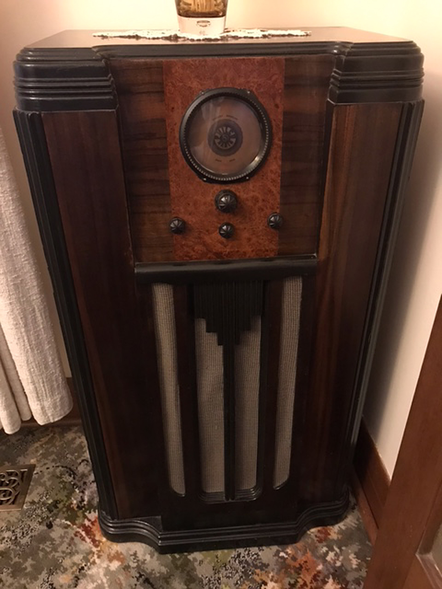 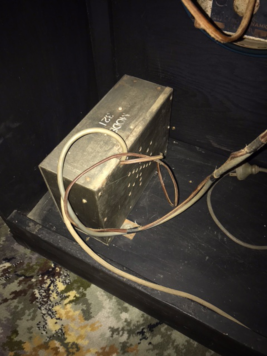  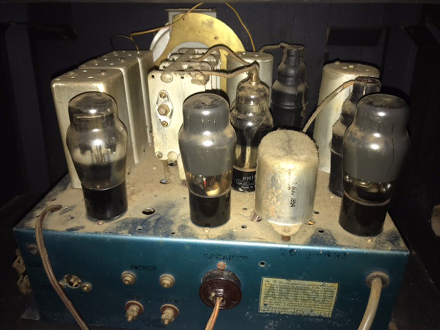 |
|
|
Return to top of page · Post #: 2 · Written at 11:40:58 PM on 25 September 2021.
|
|

|
Administrator
Location: Naremburn, NSW
Member since 15 November 2005 Member #: 1 Postcount: 7624 |
|
Photos uploaded. ‾‾‾‾‾‾‾‾‾‾‾‾‾‾‾‾‾‾‾‾‾‾‾‾‾‾‾‾‾‾‾‾‾‾‾‾‾‾‾‾‾‾‾‾‾‾‾‾‾‾‾‾‾‾‾‾‾‾‾‾‾‾‾‾‾‾‾‾ A valve a day keeps the transistor away... |
|
|
Return to top of page · Post #: 3 · Written at 11:48:00 PM on 25 September 2021.
|
|

|
Location: Sydney, NSW
Member since 28 January 2011 Member #: 823 Postcount: 6949 |
|
... meanwhile, what's the valve line-up? |
|
|
Return to top of page · Post #: 4 · Written at 2:38:09 AM on 26 September 2021.
|
|

|
Location: Hill Top, NSW
Member since 18 September 2015 Member #: 1801 Postcount: 2254 |
|
If there's a solid-state rectifier, what's that valve rectifier doing there? Just for looks? |
|
|
Return to top of page · Post #: 5 · Written at 7:22:49 AM on 26 September 2021.
|
|
|
|
Administrator
Location: Naremburn, NSW
Member since 15 November 2005 Member #: 1 Postcount: 7624 |
|
The two output valves are probably just different brands. ‾‾‾‾‾‾‾‾‾‾‾‾‾‾‾‾‾‾‾‾‾‾‾‾‾‾‾‾‾‾‾‾‾‾‾‾‾‾‾‾‾‾‾‾‾‾‾‾‾‾‾‾‾‾‾‾‾‾‾‾‾‾‾‾‾‾‾‾ A valve a day keeps the transistor away... |
|
|
Return to top of page · Post #: 6 · Written at 9:12:26 AM on 26 September 2021.
|
|
|
|
Location: Belrose, NSW
Member since 31 December 2015 Member #: 1844 Postcount: 2710 |
|
Looks like a battery set that's been heavily modified. Many were. |
|
|
Return to top of page · Post #: 7 · Written at 9:42:02 AM on 26 September 2021.
|
|
|
|
Location: Melbourne, VIC
Member since 26 December 2010 Member #: 794 Postcount: 401 |
|
I’ll post the valve lineup today. |
|
|
Return to top of page · Post #: 8 · Written at 1:48:26 PM on 26 September 2021.
|
|
|
|
Location: Melbourne, VIC
Member since 26 December 2010 Member #: 794 Postcount: 401 |
|
Valve lineup is difficult as majority no longer have their labels on them. |
|
|
Return to top of page · Post #: 9 · Written at 2:28:01 PM on 26 September 2021.
|
|
|
|
Location: Hill Top, NSW
Member since 18 September 2015 Member #: 1801 Postcount: 2254 |
|
Are the valves all octal types? |
|
|
Return to top of page · Post #: 10 · Written at 2:41:49 PM on 26 September 2021.
|
|

|
Location: Wangaratta, VIC
Member since 21 February 2009 Member #: 438 Postcount: 5715 |
|
We can speculate that with what is likely 5Y3 / #80 LH on the rear view that's the rectifier & looks like one. 6J8 is late 30's and superseded other Pentagrids where there was SW. It will be the mixer / oscillator. 6U7 is a cranky RF Pentode when unshielded and can be a pre-amp ahead of 6J8 and the first IF after it. |
|
|
Return to top of page · Post #: 11 · Written at 2:45:46 PM on 26 September 2021.
|
|

|
Location: Tamworth, NSW
Member since 6 April 2012 Member #: 1126 Postcount: 472 |
|
That output transformer isnt original. There is a Philco group on facebook. Mainly US collectors but someone locally might recognise it. Maybe start tracing the circuit if you can. |
|
|
Return to top of page · Post #: 12 · Written at 3:03:00 PM on 26 September 2021.
|
|
|
|
Location: Sydney, NSW
Member since 28 January 2011 Member #: 823 Postcount: 6949 |
|
Valve lineup is difficult as majority no longer have their labels on them. |
|
|
Return to top of page · Post #: 13 · Written at 5:00:43 PM on 26 September 2021.
|
|
|
|
Administrator
Location: Naremburn, NSW
Member since 15 November 2005 Member #: 1 Postcount: 7624 |
|
Could be a NZ produced set as well. ‾‾‾‾‾‾‾‾‾‾‾‾‾‾‾‾‾‾‾‾‾‾‾‾‾‾‾‾‾‾‾‾‾‾‾‾‾‾‾‾‾‾‾‾‾‾‾‾‾‾‾‾‾‾‾‾‾‾‾‾‾‾‾‾‾‾‾‾ A valve a day keeps the transistor away... |
|
|
Return to top of page · Post #: 14 · Written at 7:00:43 PM on 26 September 2021.
|
|
|
|
Location: Linton, VIC
Member since 30 December 2016 Member #: 2028 Postcount: 472 |
|
Three transformers!!! |
|
|
Return to top of page · Post #: 15 · Written at 8:53:11 PM on 26 September 2021.
|
|
|
|
Location: Hill Top, NSW
Member since 18 September 2015 Member #: 1801 Postcount: 2254 |
|
There are two valves next to the tuning gang. |
|
|
You need to be a member to post comments on this forum.
|
|

Sign In
Vintage Radio and Television is proudly brought to you by an era where things were built with pride and made to last.
DISCLAIMER: Valve radios and televisions contain voltages that can deliver lethal shocks. You should not attempt to work on a valve radio or other electrical appliances unless you know exactly what you are doing and have gained some experience with electronics and working around high voltages. The owner, administrators and staff of Vintage Radio & Television will accept no liability for any damage, injury or loss of life that comes as a result of your use or mis-use of information on this website. Please read our Safety Warning before using this website.
WARNING: Under no circumstances should you ever apply power to a vintage radio, television or other electrical appliance you have acquired without first having it checked and serviced by an experienced person. Also, at no time should any appliance be connected to an electricity supply if the power cord is damaged. If in doubt, do not apply power.
Shintara - Keepin' It Real · VileSilencer - Maintain The Rage