
Tech Talk
Forum home - Go back to Tech talk
|
Royaltone
|
|
|
Return to top of page · Post #: 1 · Written at 3:30:19 PM on 11 September 2021.
|
|
|
|
Location: Melbourne, VIC
Member since 26 December 2010 Member #: 794 Postcount: 401 |
|
Hi there, 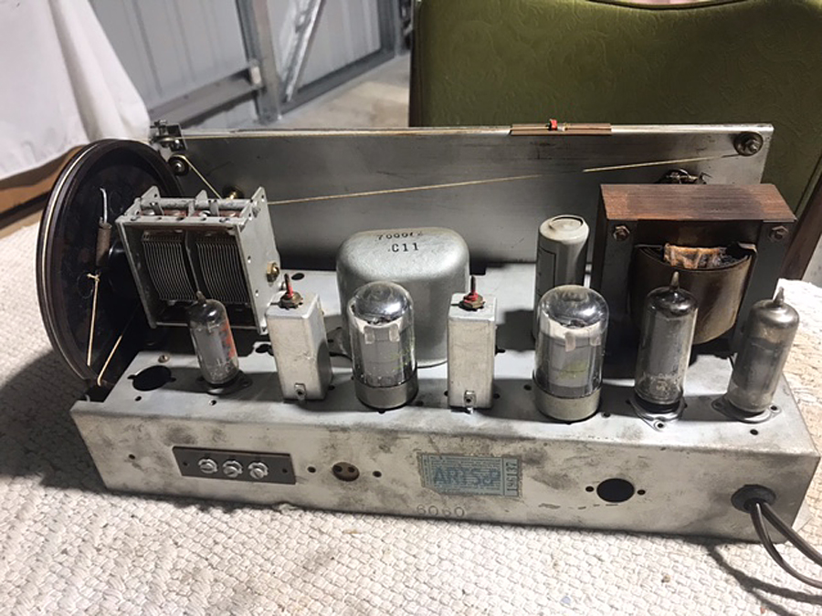 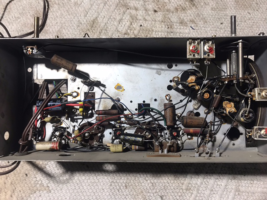 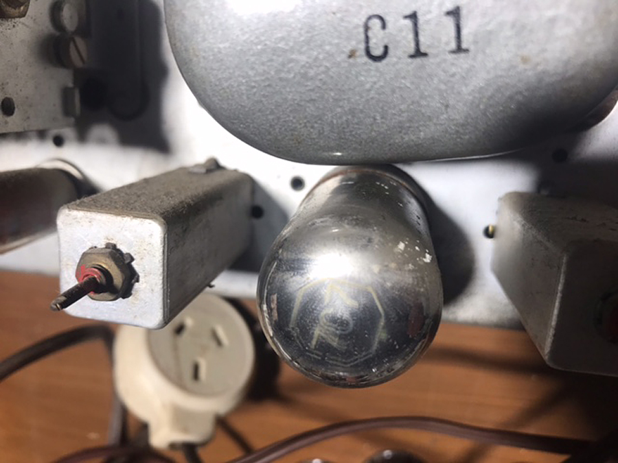 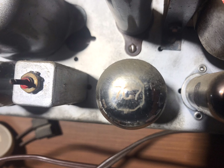 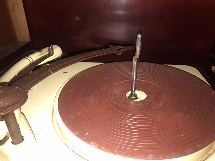 |
|
|
Return to top of page · Post #: 2 · Written at 8:18:00 PM on 11 September 2021.
|
|

|
Location: Hill Top, NSW
Member since 18 September 2015 Member #: 1801 Postcount: 2254 |
|
Got a photo of it? It might be something else rebadged. |
|
|
Return to top of page · Post #: 3 · Written at 8:21:32 PM on 11 September 2021.
|
|

|
Location: Sydney, NSW
Member since 28 January 2011 Member #: 823 Postcount: 6949 |
|
Royaltone has the ring of a house brand name, and seems it was according to the Radiomuseum:
What is the valve line-up? We may be able to identify the chassis from that. Some good clear photos may help identify the turntable. |
|
|
Return to top of page · Post #: 4 · Written at 10:56:03 AM on 12 September 2021.
|
|
|
|
Location: Melbourne, VIC
Member since 26 December 2010 Member #: 794 Postcount: 401 |
|
Hi gents, |
|
|
Return to top of page · Post #: 5 · Written at 4:35:21 PM on 12 September 2021.
|
|
|
|
Location: Belrose, NSW
Member since 31 December 2015 Member #: 1844 Postcount: 2710 |
|
Late 50s, early 60s. Those Loc-fit tubes were rarely seen here. Sounds like a small manufacturer that got a special deal on them. |
|
|
Return to top of page · Post #: 6 · Written at 4:43:34 PM on 12 September 2021.
|
|

|
Location: Wangaratta, VIC
Member since 21 February 2009 Member #: 438 Postcount: 5715 |
|
May have been Astor that must have got a good deal on EF 50 Loctal's as they appeared in their IF's of some models. |
|
|
Return to top of page · Post #: 7 · Written at 6:51:55 PM on 12 September 2021.
|
|
|
|
Location: Sydney, NSW
Member since 28 January 2011 Member #: 823 Postcount: 6949 |
|
Once I know how to upload pics, I’ll post them. |
|
|
Return to top of page · Post #: 8 · Written at 7:26:31 PM on 12 September 2021.
|
|
|
|
Location: Melbourne, VIC
Member since 26 December 2010 Member #: 794 Postcount: 401 |
|
Thanks guys, I’ve emailed some pics to Brad, once they’re up it will be interesting to hear your thoughts |
|
|
Return to top of page · Post #: 9 · Written at 12:49:35 AM on 13 September 2021.
|
|

|
Administrator
Location: Naremburn, NSW
Member since 15 November 2005 Member #: 1 Postcount: 7624 |
|
Photos uploaded. ‾‾‾‾‾‾‾‾‾‾‾‾‾‾‾‾‾‾‾‾‾‾‾‾‾‾‾‾‾‾‾‾‾‾‾‾‾‾‾‾‾‾‾‾‾‾‾‾‾‾‾‾‾‾‾‾‾‾‾‾‾‾‾‾‾‾‾‾ A valve a day keeps the transistor away... |
|
|
Return to top of page · Post #: 10 · Written at 12:33:21 PM on 13 September 2021.
|
|
|
|
Location: Hill Top, NSW
Member since 18 September 2015 Member #: 1801 Postcount: 2254 |
|
I've never seen any of those 7-series valves before. If it wasn't for them I'd say it's a standard 5-valve radio. |
|
|
Return to top of page · Post #: 11 · Written at 12:49:11 PM on 13 September 2021.
|
|
|
|
Location: Melbourne, VIC
Member since 26 December 2010 Member #: 794 Postcount: 401 |
|
Thanks, that’s the plan though there seems to be a short somewhere. There are 2 x 120ohm resistors, 1 of which goes to the negative side of the 24μF electrolytic cap to ground. When switched on, it immediately overheats. The dial lights are also dim. Removing the 6X4 rectifier valve sees the dial lights return to normal brightness and no volts at the 24μF cap. I’d like to know what voltage should be there as there may be an issue with the transformer itself. The 24μF has been replaced. |
|
|
Return to top of page · Post #: 12 · Written at 4:26:50 PM on 13 September 2021.
|
|
|
|
Location: Sydney, NSW
Member since 28 January 2011 Member #: 823 Postcount: 6949 |
|
I’d like to know what voltage should be there |
|
|
Return to top of page · Post #: 13 · Written at 10:03:42 PM on 13 September 2021.
|
|
|
|
Location: Hill Top, NSW
Member since 18 September 2015 Member #: 1801 Postcount: 2254 |
|
I think we need to do some tests with the 6X4 out. Firstly power-off, unplug mains cord. Multimeter to ohms. Check resistance between 24μF - 120 ohm junction (I'll call this point X from now), and each of the 6X4 anodes. Should be the same for each anode. Now measure between one anode and the other - should be twice as much resistance. Lastly, measure between point X and chassis - 120 ohms. |
|
|
Return to top of page · Post #: 14 · Written at 10:17:25 PM on 13 September 2021.
|
|
|
|
Location: Melbourne, VIC
Member since 26 December 2010 Member #: 794 Postcount: 401 |
|
Thanks for be that, I changed the 24μF cap it’s 600v rated. |
|
|
Return to top of page · Post #: 15 · Written at 10:21:43 PM on 13 September 2021.
|
|
|
|
Location: Wangaratta, VIC
Member since 21 February 2009 Member #: 438 Postcount: 5715 |
|
If there is no PSU circuit draw it. If the set is back biased, the CT will ground via the 120R. the 24μF cap is from CT to ground. If there is a cap CT to chassis It will be negative to CT, positive to chassis. |
|
|
You need to be a member to post comments on this forum.
|
|
Sign In
Vintage Radio and Television is proudly brought to you by an era where things were built with pride and made to last.
DISCLAIMER: Valve radios and televisions contain voltages that can deliver lethal shocks. You should not attempt to work on a valve radio or other electrical appliances unless you know exactly what you are doing and have gained some experience with electronics and working around high voltages. The owner, administrators and staff of Vintage Radio & Television will accept no liability for any damage, injury or loss of life that comes as a result of your use or mis-use of information on this website. Please read our Safety Warning before using this website.
WARNING: Under no circumstances should you ever apply power to a vintage radio, television or other electrical appliance you have acquired without first having it checked and serviced by an experienced person. Also, at no time should any appliance be connected to an electricity supply if the power cord is damaged. If in doubt, do not apply power.
Shintara - Keepin' It Real · VileSilencer - Maintain The Rage