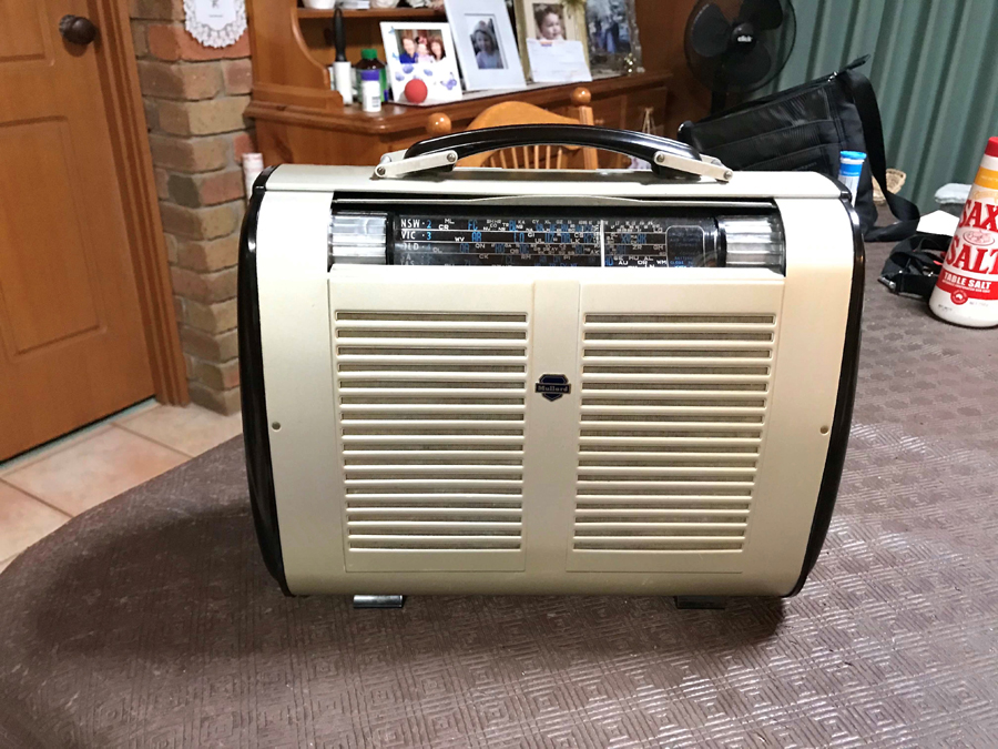
I recently purchased a Mullard MABS 1052 on EBay, these a rebadging of the Philips 148, they use 5 x miniature 1.4 volt filament valves.
This is battery/electric portable from the 1954 era, The radio was purchased with the view to get it operational, these radios are my favourite repairer
and I’ve purchased a few of these over the years varying states of disrepair, the 240 VAC powered versions are the only ones that I’m interested in.
A detailed restoration of the Philips version 148C was shown I Silicon Chip March 2018
What I liked about this one from the auction site was the pictures of the radio, it appeared un- molested, and it had a full compliment of valves, and internally it was complete and as a added bonus it came supplied with its dedicated power cord, these original dedicated two pin plug leads are very hard to come by.
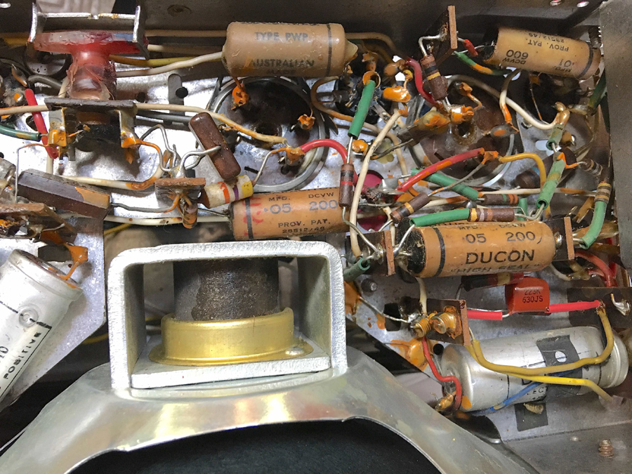
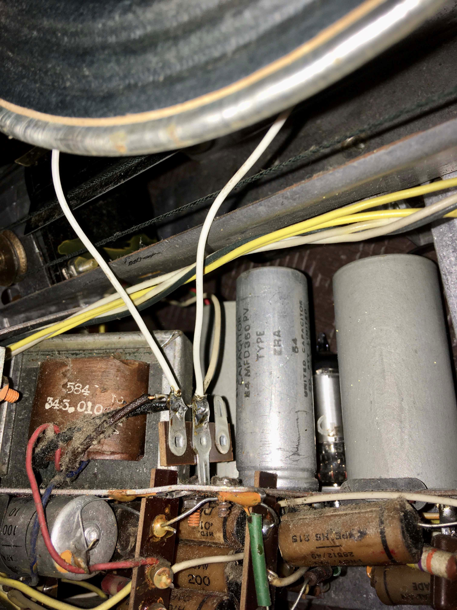
Servicing these is straight forward but you do have to remove the chassis from the case to access most under chassis components and removing the speaker to gain access to the top mounted components . The power transformer is tacked on to the right side of the chassis for 240 VAC volt operation.
….Troubleshooting the Mullard MABS1052 / Philips 148
When this was plugged into the 240 volt mains, probably for the first time in many years and after the valves warm up time, there was nothing, the set was completely dead, so next step was to remove the chassis from the case. First you have to unsolder and remove the two aerial coil wires that run from the chassis to the coils on the left hand side of the bakelite case end.
With the chassis removed and propped up in vertical position and with mains power turned on there was still no joy, the chassis was then moved from the vertical to a horizontal position then it demonstrated a low grade crackling from the speaker.
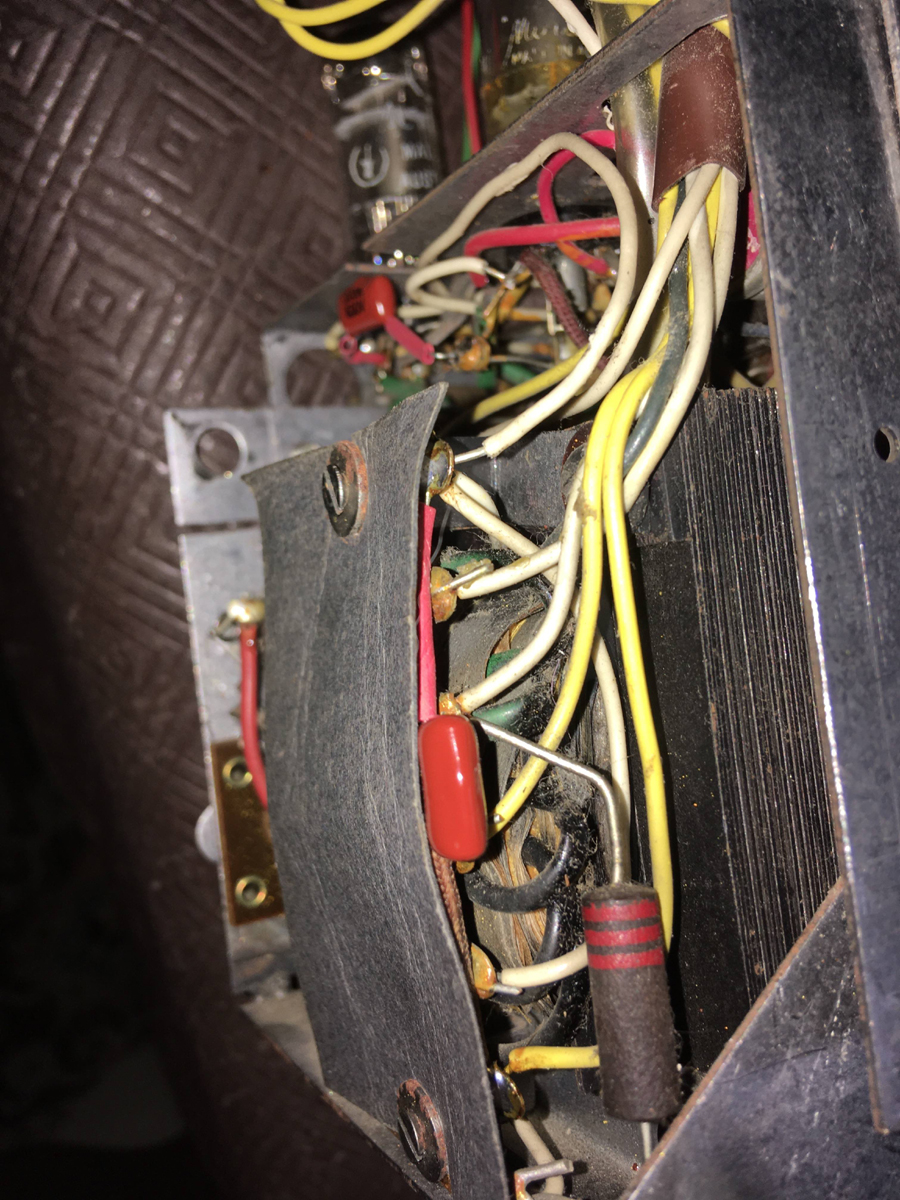
Moving it through these positions a few times gave, the same results again , on and off again, probing the speaker transformer secondary on the three pin tag strip , behind where the speaker sits, bought the crackling back.
The fault it appears was, the earthed secondary wire from the output transformer was wrapped around the lug but not soldered. It does seem it left the factory
like that.
The previous owner must have been very frustrated with the sound cutting in and out because the volume knob was worked very hard and had split internally on the shaft, the volume control mounting plate was also bent, all this effort trying to get this intermittent radio back to life. The Mullard more than likely would have functioned ok when the transformer wires were tinned bright when the set was new, but put a few years of atmospheric corrosion on those transformer output leads and this radio would have had a very intermittent sound output as was the case here.
After re-soldering the speaker secondary leads, the Mullard now had hum with low grade buzz from the speaker which disappeared to silence after a few minutes, a check of the voltage on C22 , ( 24μF 350 v electrolytic ), the working B+ for the set showed 25VDC at this point which was exceedingly low and should have been in the order of 90 volts.
The output from the 6V4 rectifier gave a reading at 130VDC at R15, so I concluded the 6V4 was within specs.
As the DC voltage after the dropping resistors, was down, I measured resistance from the plate of the 3V4 output valve to earth, it was showing only a few kilo-ohms, this was my first choice capacitor, fitted to prevent oscillation ( circuit no. C21 ) is a 0.02μF 400volt capacitor, and due to operating voltage and age these capacitors being leaky was no surprise.
Taking this out of circuit and measuring this with the Fluke, it read 3000 ohms, it was certainly leaky and even as leaky as it was there was no visual signs of heat distress from this mylar capacitor. On a side note, sometimes a shorted or leaky capacitor on a B+ rail can be seen with its wax coating dripping and can be warm but there were no visuals in this case.
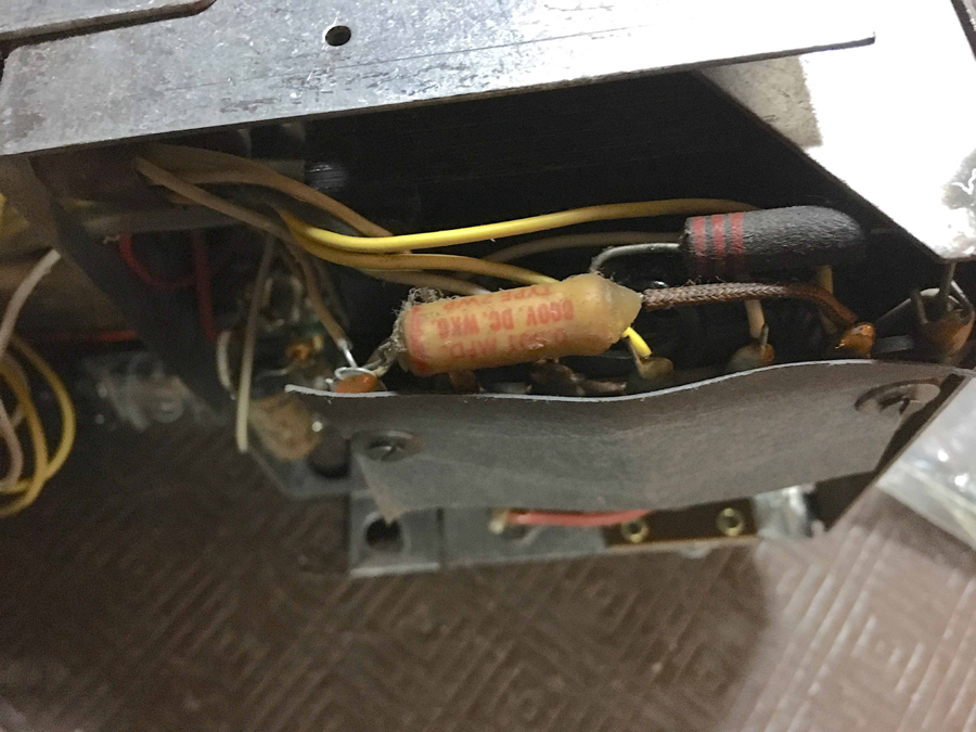
Another capacitor in these models, which should be the first capacitor you should replace is the is C30 (0.001μF 600volt) across the secondary of the power transformer to earth, to reduce induced modulation hum into RF circuits, this capacitor is soldered directly on the power transformer tag strip and, is easy to miss because of its placement. If this paper capacitor shorts out and you are not aware of its breakdown the power transformer will suffer and it can happen quick.
The aluminium case of the radio looked good and the bakelite ends had no chips and polished up well, the dial cover was very yellowed with age and a replacement one was formed. I cut out and used hot water to help form A4 0.08mm clear acetate sheet for the dial cover which is available from Officeworks.
Voltages around the Mullard were within specs, filament voltages for the valves checked ok, more components could be replaced to increase future reliability.
The Mullard MABS1052 worked surprisingly good pulling in Radio Stations 1000km with ease. These a truly a great radio from the early 1950’s representing an interesting era in radio.
Pictures coming...thankyou Guys
Mullard MABS1052 Circuit Diagram