
Tech Talk
Forum home - Go back to Tech talk
|
1931 'potted' power supply
|
|
|
Return to top of page · Post #: 1 · Written at 5:05:32 PM on 29 August 2020.
|
|
|
|
Location: Mount Lawley, WA
Member since 12 September 2017 Member #: 2167 Postcount: 49 |
|
I recently acquired an Emmco Troubadour 7 console radio. 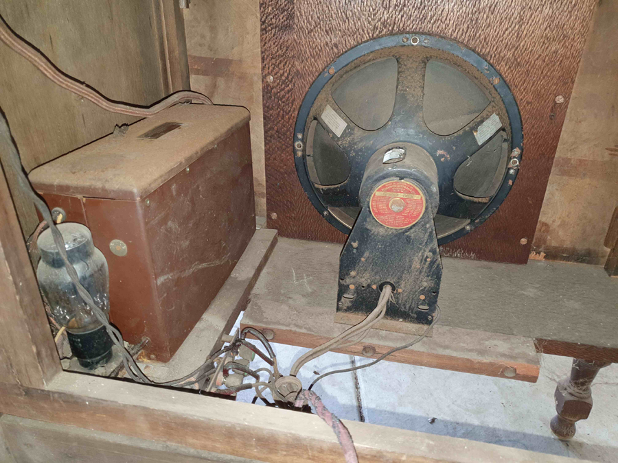 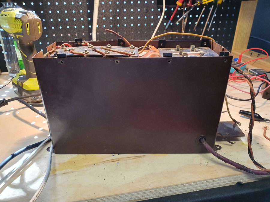 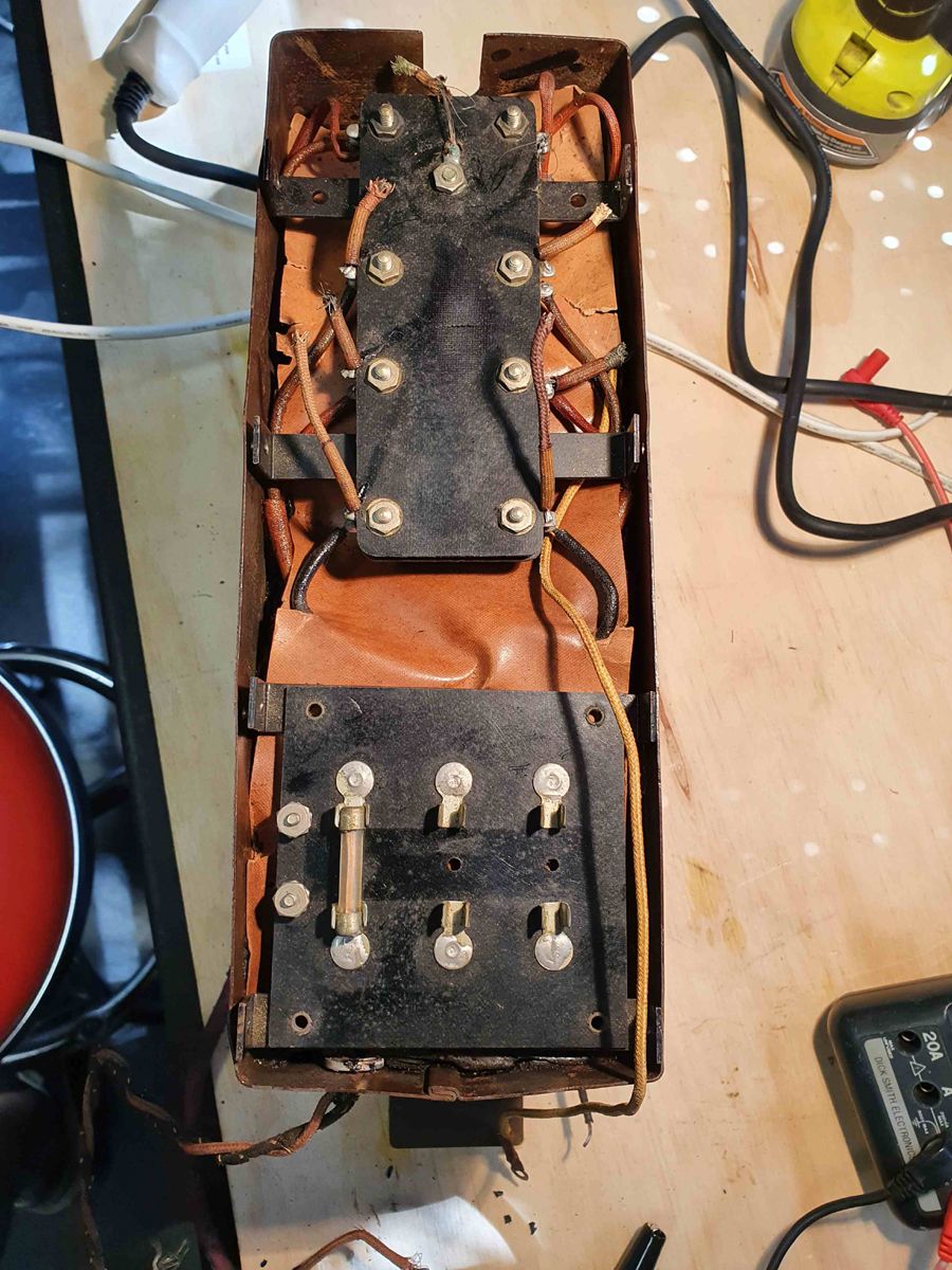 |
|
|
Return to top of page · Post #: 2 · Written at 8:38:15 PM on 29 August 2020.
|
|

|
Administrator
Location: Naremburn, NSW
Member since 15 November 2005 Member #: 1 Postcount: 7638 |
|
Photos uploaded. ‾‾‾‾‾‾‾‾‾‾‾‾‾‾‾‾‾‾‾‾‾‾‾‾‾‾‾‾‾‾‾‾‾‾‾‾‾‾‾‾‾‾‾‾‾‾‾‾‾‾‾‾‾‾‾‾‾‾‾‾‾‾‾‾‾‾‾‾ A valve a day keeps the transistor away... |
|
|
Return to top of page · Post #: 3 · Written at 8:45:54 PM on 29 August 2020.
|
|
|
|
Location: Mount Lawley, WA
Member since 12 September 2017 Member #: 2167 Postcount: 49 |
|
A few productive hours - unsoldered the paxolin boards and had a peek at whats below the oil paper. |
|
|
Return to top of page · Post #: 4 · Written at 1:30:58 AM on 30 August 2020.
|
|

|
Location: Hill Top, NSW
Member since 18 September 2015 Member #: 1801 Postcount: 2259 |
|
I almost want to jump through the screen and clean that valve... they look so much nicer. |
|
|
Return to top of page · Post #: 5 · Written at 7:05:39 AM on 30 August 2020.
|
|
|
|
Administrator
Location: Naremburn, NSW
Member since 15 November 2005 Member #: 1 Postcount: 7638 |
|
When I did instrument fitting work experience with the gas works at Mortlake one of the regular jobs was to change batteries on some sort of monitoring device that was located all over Sydney's gas network. There were three alkaline D cells inside a metal package, similar to that in the photos but a lot smaller of course. The batteries were embedded in a pitch-like substance for waterproofing/anti-corrosion purposes although by the time I did this, it was probably epoxy. We are talking 1987. ‾‾‾‾‾‾‾‾‾‾‾‾‾‾‾‾‾‾‾‾‾‾‾‾‾‾‾‾‾‾‾‾‾‾‾‾‾‾‾‾‾‾‾‾‾‾‾‾‾‾‾‾‾‾‾‾‾‾‾‾‾‾‾‾‾‾‾‾ A valve a day keeps the transistor away... |
|
|
Return to top of page · Post #: 6 · Written at 10:48:30 AM on 31 August 2020.
|
|
|
|
Location: Mount Lawley, WA
Member since 12 September 2017 Member #: 2167 Postcount: 49 |
|
Partial success so far - still more to do. |
|
|
Return to top of page · Post #: 7 · Written at 12:57:01 PM on 31 August 2020.
|
|
|
|
Location: Melbourne, VIC
Member since 11 July 2012 Member #: 1179 Postcount: 65 |
|
Do you really need to extract or 'un-pitch' the transformer/choke? If lead in wire has deteriorated, then maybe that can still be managed without de-pitching. |
|
|
Return to top of page · Post #: 8 · Written at 1:42:14 PM on 31 August 2020.
|
|
|
|
Location: Mount Lawley, WA
Member since 12 September 2017 Member #: 2167 Postcount: 49 |
|
The LT leads are all fine. |
|
|
Return to top of page · Post #: 9 · Written at 5:08:46 PM on 31 August 2020.
|
|
|
|
Location: Melbourne, VIC
Member since 11 July 2012 Member #: 1179 Postcount: 65 |
|
I did a 'short cut' with one transformer, and just carefully soldered new cable on to where the pitch was mechanically holding the lead out wire fairly well in position, and then taped the new wire down so it wouldn't move and did a megger test. But also done the full pitch crack and melt - a very ugly path to take, and the only redeeming aspect of that recovery was that the lead in wires terminated on tabs on the outer winding layer (rather than being buried in to the winding layers). |
|
|
Return to top of page · Post #: 10 · Written at 10:23:31 PM on 31 August 2020.
|
|

|
Location: Wangaratta, VIC
Member since 21 February 2009 Member #: 438 Postcount: 5730 |
|
My experience with pitch is not with a cabinet that big but needless to say, cunning & perseverance will win. A seriously hot knife can work wonders. To free it from its shell its the wrong way up. I would suggest, without looking at the top that the pitch is not all that thick. |
|
|
Return to top of page · Post #: 11 · Written at 12:34:18 PM on 1 September 2020.
|
|
|
|
Location: Belrose, NSW
Member since 31 December 2015 Member #: 1844 Postcount: 2712 |
|
I have used hot melt glue for potting things like this with great success. Once assembled and the sticks inserted, warm it up in an oven. |
|
|
Return to top of page · Post #: 12 · Written at 1:20:31 PM on 1 September 2020.
|
|
|
|
Location: Wangaratta, VIC
Member since 21 February 2009 Member #: 438 Postcount: 5730 |
|
Even that there is no one to object to some of the stuff that goes into the kitchen oven here, there would be some trepidation in respect of any parts sealed with wax. At this point I have no indication that the works & cover have been separated? |
|
|
Return to top of page · Post #: 13 · Written at 2:50:39 PM on 1 September 2020.
|
|
|
|
Location: Mount Lawley, WA
Member since 12 September 2017 Member #: 2167 Postcount: 49 |
|
The choke & Transformer were totally encapsulated in pitch. |
|
|
Return to top of page · Post #: 14 · Written at 9:49:24 PM on 1 September 2020.
|
|
|
|
Location: Wangaratta, VIC
Member since 21 February 2009 Member #: 438 Postcount: 5730 |
|
Some of that pitch, I am sure, has a high sulphur content and is quite destructive; Not only from the sulphur, but when it cracks. In cases of fragile transformer wire, I will often place a tag strip/s and wire to it first, with slack wire, this to remove any chance of "pulling" on those fragile wires. |
|
|
Return to top of page · Post #: 15 · Written at 10:59:07 AM on 2 September 2020.
|
|
|
|
Location: Mount Lawley, WA
Member since 12 September 2017 Member #: 2167 Postcount: 49 |
|
Thanks for the tips Marc. 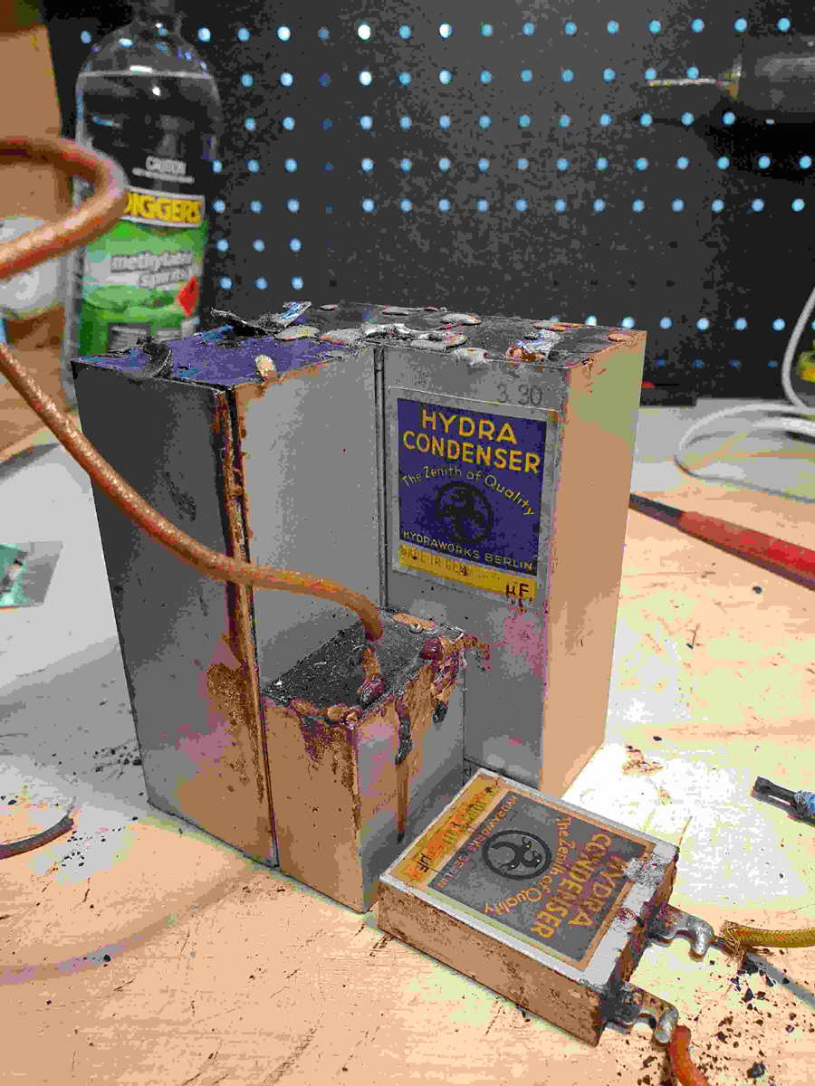 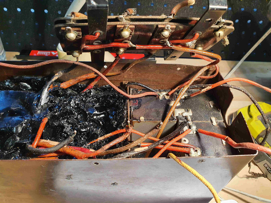 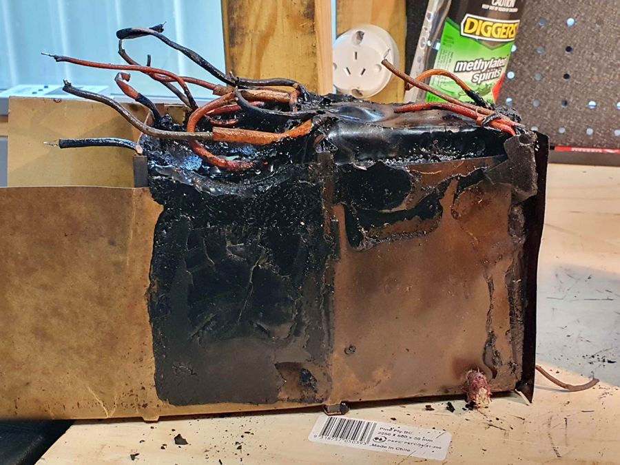  |
|
|
You need to be a member to post comments on this forum.
|
|
Sign In
Vintage Radio and Television is proudly brought to you by an era where things were built with pride and made to last.
DISCLAIMER: Valve radios and televisions contain voltages that can deliver lethal shocks. You should not attempt to work on a valve radio or other electrical appliances unless you know exactly what you are doing and have gained some experience with electronics and working around high voltages. The owner, administrators and staff of Vintage Radio & Television will accept no liability for any damage, injury or loss of life that comes as a result of your use or mis-use of information on this website. Please read our Safety Warning before using this website.
WARNING: Under no circumstances should you ever apply power to a vintage radio, television or other electrical appliance you have acquired without first having it checked and serviced by an experienced person. Also, at no time should any appliance be connected to an electricity supply if the power cord is damaged. If in doubt, do not apply power.
Shintara - Keepin' It Real · VileSilencer - Maintain The Rage