Welcome to Australia's only Vintage Radio and Television discussion forums. You are not logged in. Please log in below, apply for an account or retrieve your password.
Australian Vintage Radio Forums
  Home  ·  About Us  ·  Discussion Forums  ·  Glossary  ·  Outside Links  ·  Policies  ·  Services Directory  ·  Safety Warnings  ·  Tutorials

Tech Talk

Forum home - Go back to Tech talk

 STC 3 band with Edison phono (model 830)
« Back · 1 · 2 · 3 · Next »
 Return to top of page · Post #: 1 · Written at 3:05:39 PM on 1 June 2010.
Vintagetas's Gravatar
 Location: Hobart, TAS
 Member since 1 June 2010
 Member #: 677
 Postcount: 8

Desperately seeking a circuit diagram for this model. It requires an overhaul of the output stages to the phono (which is not installed as I purchased the radio without the phono).

Any assistance on this strange model (I think it may be very rare) would be very much appreciated.


 Return to top of page · Post #: 2 · Written at 11:08:04 PM on 1 June 2010.
Marcc's avatar
 Location: Wangaratta, VIC
 Member since 21 February 2009
 Member #: 438
 Postcount: 5267

It's 1938

Should have 3, 6U7's RF; 6T7 tuning indicator; A not common later in SW 6A8 as the converter; 6H6 detector; 6J7 first audio, 6F6 output; 5Z4 rectifier ....slower warmup than 5Y3 as it has a cathode connected to filaments.

The phono inputs. If set has never been overhauled then all of the paper caps & electrolytics should be replaced, to avoid disaster & check all of the mains wiring.

I will send circuit to Brad.

Marc


 Return to top of page · Post #: 3 · Written at 3:04:18 PM on 3 June 2010.
Vintagetas's Gravatar
 Location: Hobart, TAS
 Member since 1 June 2010
 Member #: 677
 Postcount: 8

Hi Marc,

Thank you very much for the info and for organising the circuit diagram.

I will replace the paper and electro caps. A job made easy with the circuit diagram. I presume Brad will forward the circuit diagram to me.

I will let you know how I get on with the overhaul.

I wonder if you may have any info on the Edison Phono? As I mentioned, the phono is missing. If I can get some info on the phono, I may be able to track one down. Here's hoping!

Thanks again Marc. It is always a pleasure to come accross someone that is willing to help out.

Best regards
Vince


 Return to top of page · Post #: 4 · Written at 12:06:25 AM on 4 June 2010.
Marcc's avatar
 Location: Wangaratta, VIC
 Member since 21 February 2009
 Member #: 438
 Postcount: 5267

No clues on the Phono but someone may know.

I would assume Brad will forward circuit.

Beware of work done by others.

I have mistakes in the Radiogram I am working on. Last months best score for outside entries was in a 16 valve radio, 10 dry joints & a coupling error. Other than that, the wiring was quite tatty & I had to fix that as well.

Marc


 Return to top of page · Post #: 5 · Written at 8:41:48 PM on 5 June 2010.
Brad's avatar
 Administrator
 Location: Naremburn, NSW
 Member since 15 November 2005
 Member #: 1
 Postcount: 7311

G'day all,

The circuit diagram has been forwarded and will be published here later tonight. My apologies for the late response - work has kept me off the site this week.


‾‾‾‾‾‾‾‾‾‾‾‾‾‾‾‾‾‾‾‾‾‾‾‾‾‾‾‾‾‾‾‾‾‾‾‾‾‾‾‾‾‾‾‾‾‾‾‾‾‾‾‾‾‾‾‾‾‾‾‾‾‾‾‾‾‾‾‾
A valve a day keeps the transistor away...

 
 Return to top of page · Post #: 6 · Written at 8:58:34 PM on 5 June 2010.
Marcc's avatar
 Location: Wangaratta, VIC
 Member since 21 February 2009
 Member #: 438
 Postcount: 5267

Brad

Thanks I am sure he is eager to get it.

Diagrams are handy. fired up the RK only to find the front end oscillated? Some head scratching and consulting of the circuit diagram (started without one) caused the realisation that there were two 70pF caps I needed to check (both duds) & I had not replaced the screen bypass cap as it was not there?

Could have been why the thing was abandoned? Now to fly blind on a Collaro RC54 Record changer, that has been fiddled with and has dry grease to remove (easy), or none.

Marc


 Return to top of page · Post #: 7 · Written at 6:33:01 PM on 10 June 2010.
STC830's Gravatar
 Location: NSW
 Member since 10 June 2010
 Member #: 681
 Postcount: 1263

Hi Vintegas,

I have an STC830 console but without the phono. Hence my name; joined today.
My first radio collected in 1988. Still working OK.
A few points;
-the indicator is 6T5 unfortunately rare as hen's teeth and expensive; but 6G5 works OK. 6T7 is an error on the circuit diagram.
-the only radio I have where the dial letters are etched in the glass. Therefore I was able to first carefully note the colours, wash off the old letters, repaint finishing off by scraping off the excess with a razor. I would be interested to know if yours is the same.
-knobs not original; would be interested to know what yours was fitted with
-the voltage divider had been replaced with a non standard circuit and I would like to know the resistance value of the various sections of the wire wound resistor.
-this radio has a voltage change plug on the end of the cord - don't plug it in the wrong way!

Phew a lot to ask, but anything I can help with I would be pleased to help eg I have a piece of the original speaker cloth.


 Return to top of page · Post #: 8 · Written at 9:23:03 PM on 10 June 2010.
Brad's avatar
 Administrator
 Location: Naremburn, NSW
 Member since 15 November 2005
 Member #: 1
 Postcount: 7311

G'day STC830,

Was a turntable optional on this model or is it just a case that yours is missing a turntable?


‾‾‾‾‾‾‾‾‾‾‾‾‾‾‾‾‾‾‾‾‾‾‾‾‾‾‾‾‾‾‾‾‾‾‾‾‾‾‾‾‾‾‾‾‾‾‾‾‾‾‾‾‾‾‾‾‾‾‾‾‾‾‾‾‾‾‾‾
A valve a day keeps the transistor away...

 
 Return to top of page · Post #: 9 · Written at 9:44:12 PM on 10 June 2010.
STC830's Gravatar
 Location: NSW
 Member since 10 June 2010
 Member #: 681
 Postcount: 1263

Brad

Mine is just a console radio only.
I have a vague recollection that the circuit diagram book shows a radiogram circuit; I will have to dig it out of a box in my garage.

Regards
Graham


 Return to top of page · Post #: 10 · Written at 3:15:51 PM on 11 June 2010.
Vintagetas's Gravatar
 Location: Hobart, TAS
 Member since 1 June 2010
 Member #: 677
 Postcount: 8

Thanks for the circuit diagram. It will be a huge help.

I think I should take a few pictures of my 830 and post same here. It should assist with identifying the radio correctly.

There may be a couple of 830 models?? The pictures should narrow this down. Mine has a top lid and the word "Edison" on the inside in gold leaf. It looks like there was once a phono installed.

Thanks for the info STC830. I might take you up on the speaker cloth. Mine needs to be replaced. I think that mine has the original knobs fitted. When I post the pictures, I will include a close up of the dial.

Thanks again to everyone for your help. I should post pics early next week.

My best regards to all
Vincent


 Return to top of page · Post #: 11 · Written at 5:21:45 PM on 13 June 2010.
Gfr53's Gravatar
 Location: Harston, VIC
 Member since 28 February 2009
 Member #: 442
 Postcount: 145


G'day Folks,

STC made three models with the 830 chassis. The 830R was the radiogram model. the other two where consoles.

Apart from the cabinets and the phono, (and maybe the dial), the chassis where identical.

Cheers, Graham...


 Return to top of page · Post #: 12 · Written at 12:11:53 PM on 14 June 2010.
Wa2ise's avatar
 Location: Oradell, US
 Member since 2 April 2010
 Member #: 643
 Postcount: 830

"Beware of work done by others.

I have mistakes in the Radiogram I am working on."

Reminds me of a Philco radio that came from Lima Peru. Someone changed the output tube from a loctal to an octal, changing the socket. And the rectifier. And they stuck in a transformer (220V to 120V) to replace the ballast tube. And hacked in replacement electrolytic filter caps (you seen it, the use of friction tape on spliced wires). When I first got it, I thought it was a hopeless mess. They solder mounted the transformer, but I was able to pry it out (the solder didn't go very far under the metal mounting bracket of the transformer. As for the ballast tube, I used a capacitor to series drop the 240V60Hz we have in the USA (our power companies feed us a pair of 120VAC lines, 180 degrees phase shifted, essentially center-tapped 240V with that centertap grounded) to avoid excess waste heat. And a dropping resistor to get the B+ down to around 200V. Like the old ballast would have done. Left in the octal tubes, as they were functionally equivalent to the loctals they replaced.

Seems the repair shop in Lima Peru (a sticker on the radio's back tells the name and location) had to make do with what they had on hand... In any event, it was obvious that it wasn't factory.


 Return to top of page · Post #: 13 · Written at 9:45:22 PM on 14 June 2010.
STC830's Gravatar
 Location: NSW
 Member since 10 June 2010
 Member #: 681
 Postcount: 1263

Vintagetas,

Another STC830 owner

http://www.southcom.com.au/~pauledgr/Shed.htm

Botomm RH picture

Regards
Graham


 Return to top of page · Post #: 14 · Written at 10:08:29 PM on 14 June 2010.
STC830's Gravatar
 Location: NSW
 Member since 10 June 2010
 Member #: 681
 Postcount: 1263

Vintagetas

In Australian Official Radio Service Manuals the following reference to STC radiograms:
1937 nothing
1938 nothing
1939 pick up circuit for STC receivers on page 272
1940-41 Modifications to models 509, 543, & 653 for radiogram operation on p 294

will send if needed

Regards
Graham


 Return to top of page · Post #: 15 · Written at 10:51:21 PM on 14 June 2010.
STC830's Gravatar
 Location: NSW
 Member since 10 June 2010
 Member #: 681
 Postcount: 1263

Vinteagetas

I have STC Radio 1938 Sales Manual
edited and printed by Brian T Smith in 1999. This is a reproduction of a manual that is purported to have been issued late 1937 or early 1938.

Originally it was loose leaf for later additions.
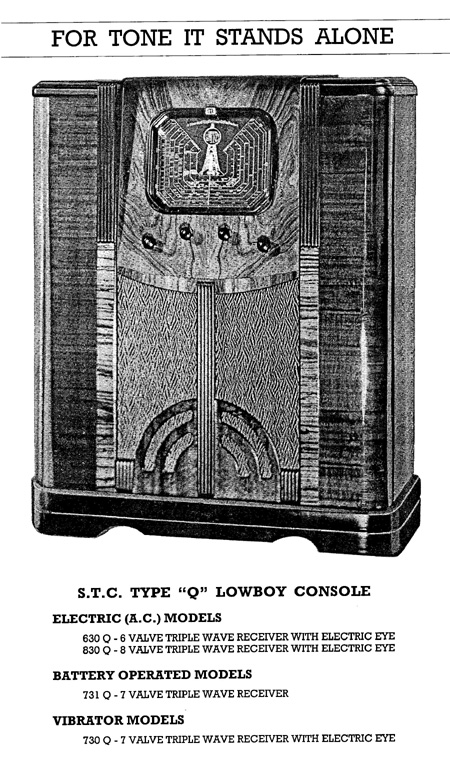
It shows the Type "Q" lowboy console which is the same as mine.
AC models 630Q & 830Q
Battery 731Q
Vibrator 730Q
all triple wave, with eye valve (except battery model)

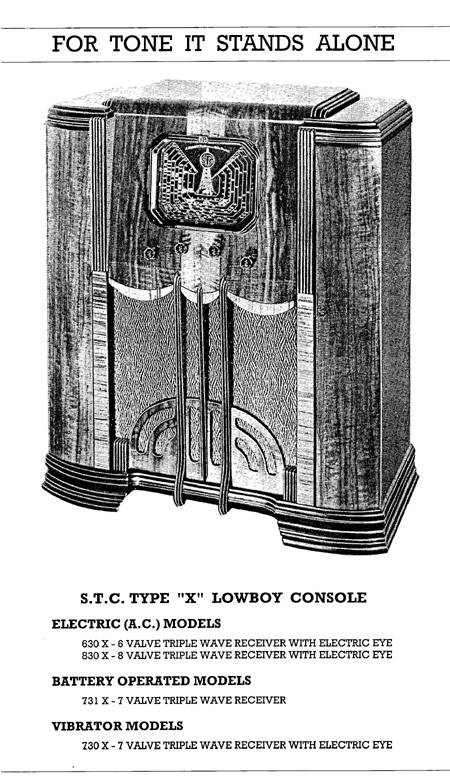
Also Type "X" lowboy console, same models as above except X instead of Q. The cabinet is wider than the type Q, the dial looks the same. The knobs are octagonal.

As you see no mention of 830R radiogram mentioned by Gfr53 so presumably these came out later in 1938.

Will post pictures when I have time to scan them.

Regards
Graham


Click on image for larger resolution


« Back · 1 · 2 · 3 · Next »
 You need to be a member to post comments on this forum.

Sign In

Username:
Password:
 Keep me logged in.
Do not tick box on a computer with public access.