
Tech Talk
Forum home - Go back to Tech talk
|
AWA PA449Y radio tuner kit option in 1960's PA amps
|
|
|
« Back ·
1 ·
Next »
|
|
|
Return to top of page · Post #: 1 · Written at 10:00:59 PM on 22 July 2020.
|
|
|
|
Location: Melbourne, VIC
Member since 11 July 2012 Member #: 1179 Postcount: 65 |
|
AWA had available a MW radio tuner module that could be fitted to their public address amplifiers of the 1960's, with a model number PA449Y. |
|
|
Return to top of page · Post #: 2 · Written at 11:45:31 PM on 22 July 2020.
|
|

|
Location: Sydney, NSW
Member since 28 January 2011 Member #: 823 Postcount: 6960 |
|
If you don't get the answer here, suggest contacting John McIlwaine, President of NSW Branch of HRSA. John worked for AWA for a long time and is a font of knowledge on most aspects and is in contact with other AWA veterans. |
|
|
Return to top of page · Post #: 3 · Written at 10:07:57 AM on 23 July 2020.
|
|

|
Location: Wangaratta, VIC
Member since 21 February 2009 Member #: 438 Postcount: 5730 |
|
This is on Kevin Chants site. https://www.kevinchant.com/uploads/7/1/0/8/7108231/pa1001_advert_awa.pdf |
|
|
Return to top of page · Post #: 4 · Written at 1:08:04 PM on 23 July 2020.
|
|
|
|
Location: Melbourne, VIC
Member since 11 July 2012 Member #: 1179 Postcount: 65 |
|
Thanks guys - I will shoot John McIlwain an email now. |
|
|
Return to top of page · Post #: 5 · Written at 9:23:55 PM on 23 July 2020.
|
|
|
|
Location: Wangaratta, VIC
Member since 21 February 2009 Member #: 438 Postcount: 5730 |
|
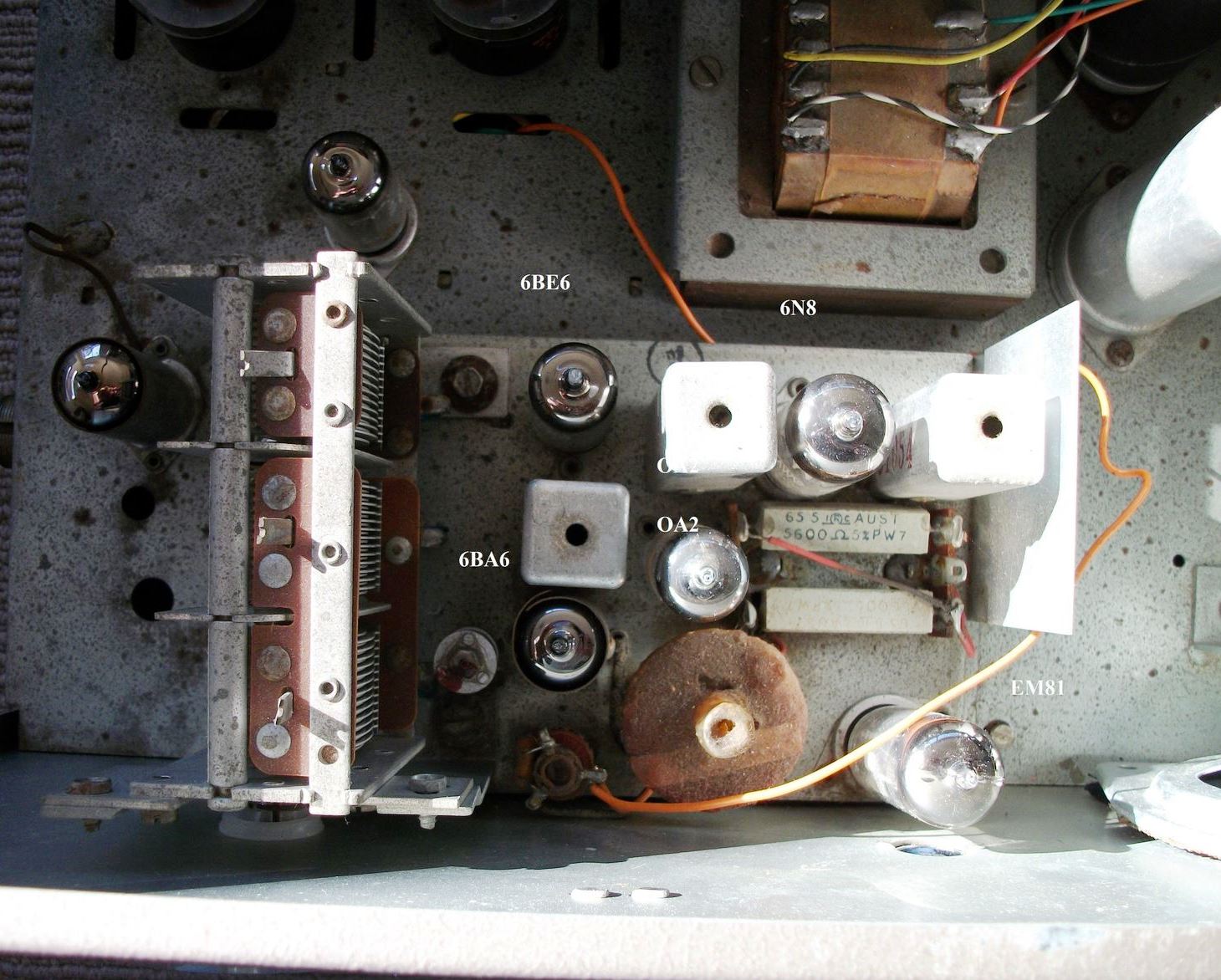
Magic eyes were more common on up market units. 3 Gangs will often be a set with an RF Pentode as a TRF stage ahead of the 6BE6. OA2 is also a bit unusual. However, at a minimum it will likely be stabilising the voltage to 6BE6. |
|
|
Return to top of page · Post #: 6 · Written at 11:25:49 PM on 23 July 2020.
|
|
|
|
Location: Melbourne, VIC
Member since 11 July 2012 Member #: 1179 Postcount: 65 |
|
The OA2 is likely used due to the supply B+ feed from the PA amplifier varying due to output power - which may have degraded tuning performance? |
|
|
Return to top of page · Post #: 7 · Written at 2:49:51 AM on 24 July 2020.
|
|
|
|
Location: Wangaratta, VIC
Member since 21 February 2009 Member #: 438 Postcount: 5730 |
|
Any variation in voltage can upset most oscillators, but one would need to see the voltages. I have a Philips "Line Amp" here & the 6CM5's class "B" PP are running at 300V 2x100mA Plate, so its add on amp would need to have it volts dropped to 250 or less. |
|
|
Return to top of page · Post #: 8 · Written at 9:28:39 AM on 29 July 2020.
|
|
|
|
Location: Melbourne, VIC
Member since 11 July 2012 Member #: 1179 Postcount: 65 |
|
It seems the main influence on B+ variation for the radio circuitry would be the EM81 and any dropper resistance (that would have been the alternative if an OA2 regulator was not used) to the main B+ in the amp. |
|
|
Return to top of page · Post #: 9 · Written at 11:35:05 AM on 29 July 2020.
|
|
|
|
Location: Belrose, NSW
Member since 31 December 2015 Member #: 1844 Postcount: 2712 |
|
I think you are missing the main reason for the OA2. |
|
|
Return to top of page · Post #: 10 · Written at 4:47:52 PM on 29 July 2020.
|
|
|
|
Location: Wangaratta, VIC
Member since 21 February 2009 Member #: 438 Postcount: 5730 |
|
Voltage will vary the EM81 a bit, however I would stick to the theory that the only way the radio part is going to stay stable, especially the oscillator is by using a regulator to maintain a constant "B" voltage to the critical parts of the radio section, or all of it. The "Radiotron hand books" (mainly) will attest to that. |
|
|
Return to top of page · Post #: 11 · Written at 4:57:40 PM on 29 July 2020.
|
|
|
|
Location: Melbourne, VIC
Member since 11 July 2012 Member #: 1179 Postcount: 65 |
|
Ian, that is what I initially presumed in post #6, however with my restored amp the 420VDC only droops to 410V when output is grossly clipping. |
|
|
Return to top of page · Post #: 12 · Written at 8:31:29 PM on 29 July 2020.
|
|
|
|
Location: Belrose, NSW
Member since 31 December 2015 Member #: 1844 Postcount: 2712 |
|
Yes but what happens if the amp is running into a too-heavy load, as commonly happens? That's the scenario AWA would have been addressing. And with cathode bias you'd be running in Class A or maybe AB1 when pushed hard. That, and the stiff power supply explains the lack of droop. |
|
|
Return to top of page · Post #: 13 · Written at 12:00:14 AM on 30 July 2020.
|
|
|
|
Location: Wangaratta, VIC
Member since 21 February 2009 Member #: 438 Postcount: 5730 |
|
I would expect with a 10V fluctuation in "B" Voltage that the tuner would be absolutely unstable. Bias, & AGC would fluctuate & as many pentagrids are voltage sensitive, its oscillator frequency would be unstable as well: Nightmare. |
|
|
« Back ·
1 ·
Next »
|
|
|
You need to be a member to post comments on this forum.
|
|
Sign In
Vintage Radio and Television is proudly brought to you by an era where things were built with pride and made to last.
DISCLAIMER: Valve radios and televisions contain voltages that can deliver lethal shocks. You should not attempt to work on a valve radio or other electrical appliances unless you know exactly what you are doing and have gained some experience with electronics and working around high voltages. The owner, administrators and staff of Vintage Radio & Television will accept no liability for any damage, injury or loss of life that comes as a result of your use or mis-use of information on this website. Please read our Safety Warning before using this website.
WARNING: Under no circumstances should you ever apply power to a vintage radio, television or other electrical appliance you have acquired without first having it checked and serviced by an experienced person. Also, at no time should any appliance be connected to an electricity supply if the power cord is damaged. If in doubt, do not apply power.
Shintara - Keepin' It Real · VileSilencer - Maintain The Rage