Welcome to Australia's only Vintage Radio and Television discussion forums. You are not logged in. Please log in below, apply for an account or retrieve your password.
Australian Vintage Radio Forums
  Home  ·  About Us  ·  Discussion Forums  ·  Glossary  ·  Outside Links  ·  Policies  ·  Services Directory  ·  Safety Warnings  ·  Tutorials

Tech Talk

Forum home - Go back to Tech talk

 AWA R155 Console circa 1936
« Back · 1 · Next »
 Return to top of page · Post #: 1 · Written at 12:45:42 AM on 25 April 2010.
Duconbuster's Gravatar
 Location: Riddells Creek, VIC
 Member since 7 August 2009
 Member #: 526
 Postcount: 123

Hoping someone can provide a legible schematic & service data for the AWA 155 console which I believe was made in 1936. Chassis is marked as R155/

Have replaced the usual suspect Ducons & I am moving on to the resistors before valve out power on. Schematic should solve two things. What is the the 2 position switch on the far right for? unit is only Broadcast band with no phono pick up terminal ?? & has a variable resistor for the tone.

Pin 4 of type 80 Rectifier has a painted carbon "dog Bone" shaped resistor for want of a better description connected to it. Paint has crumbled off so I cannot identify it fully, has yellow body representing 4. End dot colour (second digit) is black but the painted dot (multiplier) is missing due to the paint flake......So I guess HELP is needed!! It measures at 48K? was it 40K? now 8k out of tolerance? need to verify.

Valve line up for this chassis is Type 80,42,6B7,6D6 & 6A7
Thanks


 Return to top of page · Post #: 2 · Written at 10:25:48 PM on 25 April 2010.
Marcc's avatar
 Location: Wangaratta, VIC
 Member since 21 February 2009
 Member #: 438
 Postcount: 5253

Highly likely that the switch is a sensitivity control?

Common in that era albeit they knew better.

Highly likely to be in the cathode circuit of the converter, or both the converter and 1st RF if its following that plan.

Where is the resistor headed? Some of those only had two colours if they were 20, 30 or 40. More info... could be a plate resistor, could be the screen resistor for the pentodes & octode?

Marc


 Return to top of page · Post #: 3 · Written at 9:12:26 PM on 3 May 2010.
Duconbuster's Gravatar
 Location: Riddells Creek, VIC
 Member since 7 August 2009
 Member #: 526
 Postcount: 123

Yep Marcc, you are 100% correct about the sensitivity control, first one I have come across on a radio, seems a bit of a an odd feature to have.?? Especially considering cost of these radio's compared to income levels at the time it seems strange, would have been nicer if it was phono input sw!!

Have sent a pic to Brad of the part of the CCT diag in question, hope it has enough detail as time for hobbies has been a bit scant lately...

If Brad can post it or forward it to you that would great thanks

Radio schematic & details were published in RT anuual 1938 page 314, although I doubt copies of that would be easy to come by if at all..
Didn't realise there was another range of books with schematics outside the AORSM....another day another thing learned.......

Cheers all


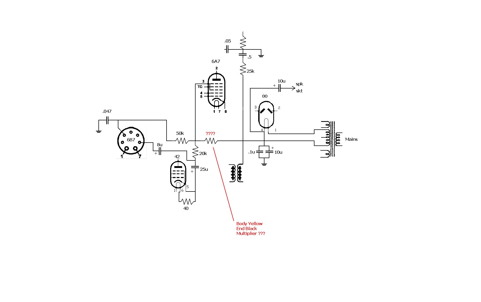
Click on image for larger resolution


 Return to top of page · Post #: 4 · Written at 12:16:40 AM on 4 May 2010.
Marcc's avatar
 Location: Wangaratta, VIC
 Member since 21 February 2009
 Member #: 438
 Postcount: 5253

Fascinating that my last posting was a comment to Brad re same publication. I have the 1937 edition. There are other Books of circuits, apart from these.

I just had dealings with a variant of an R301A of which it appears they made only one. This had a sensitivity control R301A did not. I have seen sensitivity controls, on several sets of that era.

The thing is that they knew how AGC (AVC) worked. The R301A had seperate delayed AGC The variant did as well.

These were high end as the first IF was actually a bandpass filter, then came the two more conventional IF's. (1934)

For complexity a recent US Midwest 18-34 (18 Valve 1934) had amplified AGC. Thank goodness Midwest had the real sheet on how to set this, as that data was not in Rider.

Stepped switch tone controls are not that unusual. the Philips 132L currenly featuring, has that, and its also the on/off.

Circuit is always useful. I ended up drawing the one for the R301A variant as it was different in several ways, despite the circuit being nearly the same drawing.

You may need circuit for resistor values, as early on there was no real code & manufacturers used their own. I had a 1929 Lyric (All American Mohawk, a division of Wurlitzer) in for overhaul & the ones in it were totally inconsistent with modern practice.

Fortunately its circuit was in Rider.

Forward is better for detail, however there will be other interested parties that should see it posted as well, for their info.

Time is always a balancing act. I am trying to get a Midwest 16 Valve off of the bench working. However, it will stall, as one of todays jobs will be making a "V" belt pulley, for a machine, as the broken one is unprocurable.

Marc


 Return to top of page · Post #: 5 · Written at 5:55:44 PM on 6 May 2010.
Brad's avatar
 Administrator
 Location: Naremburn, NSW
 Member since 15 November 2005
 Member #: 1
 Postcount: 7300

Image uploaded. Grin


‾‾‾‾‾‾‾‾‾‾‾‾‾‾‾‾‾‾‾‾‾‾‾‾‾‾‾‾‾‾‾‾‾‾‾‾‾‾‾‾‾‾‾‾‾‾‾‾‾‾‾‾‾‾‾‾‾‾‾‾‾‾‾‾‾‾‾‾
A valve a day keeps the transistor away...

 
 Return to top of page · Post #: 6 · Written at 12:03:30 AM on 7 May 2010.
Marcc's avatar
 Location: Wangaratta, VIC
 Member since 21 February 2009
 Member #: 438
 Postcount: 5253

Where on earth did that circuit come from?

It is liable to be unloading 570VAC across the filaments of the 5Y3 with the plates not connected.

The only thing this will do is cook the transformer if it's wired like that. There are several mistakes.

The Filaments as shown pins 1 & 4 are the big ones. B+ also comes off of those. B- comes off of the CT of the centre tap of the winding in the centre.... if its the correct one? The other two should be on the plates 2 & 3

The only way that the two fiter caps are going to be both common to 80 cathode (filament), is if there is a field coil or choke in the earth return. ie the ct goes to the speaker plug. The CT will have the negative end of the cap on it the other end will go to earth.

The 80 filaments should be on a 5V secondary winding on their own. The other winding is the 6.3V heaters.

That can be established with the valves removed an the meter on AC. The voltages will read high. If you are not sure of the HT terminations.. you can find them with an ohmmeter (SET DEAD) as they should have the highest resistance.

Ohms are not measured on a live set. The mains side should be safe, if you are going to power up. If you get the wrong connections on the HT the meter must be able to withstand more than 1KV AC (Very few will) AVO 7X will not for instance flash before 3KV, but only has a 1000V max range.

If youre not sure sit on the fingers & get help.

The cathode of the 42 is wrong and does not earth, the 40 Ohm resistor is probably its cathode resistor (pin 5) which should not be on the heater? Heaters are the big pins 1 & 6. One of those probably goes to earth which is probably at the intersection of the 25μF 25V(?) 8μF Cathode bypass minus resistor which could be as high as 2K5?

That would mean that the .047mfd (original 0.05) is a screen decoupler, the 20K is the earth end of the screen divider which could be 100K or 10K depending on how many screens are on it and what combination gives around 125V With the 50K something is radically wrong there. One could be a plate resistor or the one for the oscillator grid (probably the 20K)?

Big issues here.... Methinks back to the drawing board.

Marc


 Return to top of page · Post #: 7 · Written at 12:08:09 AM on 7 May 2010.
Marcc's avatar
 Location: Wangaratta, VIC
 Member since 21 February 2009
 Member #: 438
 Postcount: 5253

Any ideas on why my post ended up cart before the horse?

It turned up before the circuit?

loggin is also timing out on posts taking time to write?

Marc


 Return to top of page · Post #: 8 · Written at 6:01:07 AM on 7 May 2010.
Brad's avatar
 Administrator
 Location: Naremburn, NSW
 Member since 15 November 2005
 Member #: 1
 Postcount: 7300

G'day Marcc,

It does look like something has gone horribly wrong with this thread. I'll check it out tonight.


‾‾‾‾‾‾‾‾‾‾‾‾‾‾‾‾‾‾‾‾‾‾‾‾‾‾‾‾‾‾‾‾‾‾‾‾‾‾‾‾‾‾‾‾‾‾‾‾‾‾‾‾‾‾‾‾‾‾‾‾‾‾‾‾‾‾‾‾
A valve a day keeps the transistor away...

 
 Return to top of page · Post #: 9 · Written at 5:07:05 PM on 7 May 2010.
Brad's avatar
 Administrator
 Location: Naremburn, NSW
 Member since 15 November 2005
 Member #: 1
 Postcount: 7300

Okay, the order of comments seems to be fixed now. I've added an argument to the SQL statements that pick the comments out of the database which will over-ride the default setting that is supposed to work though, for some un-known reason, doesn't in this thread.

The comments are appearing in the correct order in the database so I am baffled as to what had caused the problem. Not to worry, all fixed now. Approve


‾‾‾‾‾‾‾‾‾‾‾‾‾‾‾‾‾‾‾‾‾‾‾‾‾‾‾‾‾‾‾‾‾‾‾‾‾‾‾‾‾‾‾‾‾‾‾‾‾‾‾‾‾‾‾‾‾‾‾‾‾‾‾‾‾‾‾‾
A valve a day keeps the transistor away...

 
 Return to top of page · Post #: 10 · Written at 8:54:17 PM on 7 May 2010.
Marcc's avatar
 Location: Wangaratta, VIC
 Member since 21 February 2009
 Member #: 438
 Postcount: 5253

Brad,

Looks like its sorted. It was liable to cause confusion.

I would point out again, that when trying to interpret a circuit, draw the valves and any transformers etc. Pretty much as they appear on the chassis.

After you do that you can play join the dots. Many of these sets roughly follow the same plot.

The most common are:-
For early sets: TRF
Pre Pentagrid Superhets: "Autodyne converters" These used Pentodes as mixers, sometimes with a seperate oscilator valve.
Superhetrodynes using Pentagrids: Eg Octodes 6A7, 6A8, 6AS7. or Triode Heptodes like 6J8.

Once the circuit is drawn and tidied up. You or others can quite often pick any circuit errors.

Taking Photo's prior to attacking a set can also be useful, should you get things wrong or forget where a bit came from.

Marc


 Return to top of page · Post #: 11 · Written at 12:07:42 AM on 11 May 2010.
Duconbuster's Gravatar
 Location: Riddells Creek, VIC
 Member since 7 August 2009
 Member #: 526
 Postcount: 123

Yikes didn't think I'd stuffed it up that much...will have another go & submit for posting to replace above when it's not so late at night!!!
It was only an "extract if you like of the area around the resistor in question.
Anyway between computers, vacuum cleaners & Navmans needing attention....none of which are mine...should get there in the next week or so to review.........hopefully.


 Return to top of page · Post #: 12 · Written at 10:38:23 AM on 11 May 2010.
Marcc's avatar
 Location: Wangaratta, VIC
 Member since 21 February 2009
 Member #: 438
 Postcount: 5253

Do try the join the dots method. You can do this on preferably graph type paper. This method pre-dates computers & works.

I normally draw the B+ rail in red (even on the AutoCAD) draw the wires in pencil so that you can correct easily.

Then the only question is 2B or not 2B.

Marc


 Return to top of page · Post #: 13 · Written at 2:30:53 AM on 14 May 2010.
Marcc's avatar
 Location: Wangaratta, VIC
 Member since 21 February 2009
 Member #: 438
 Postcount: 5253

Join the dots *.pdf file sent to Brad. No appologies for format, it is from two AutoCAD's & will come up badly in anything else.

If you need a *. bmp (next best) to use in paint or similar advise. Print; draw; scan; is good if you have a scanner.

Initially you can draw only that area, which is the problem.

Marc


« Back · 1 · Next »
 You need to be a member to post comments on this forum.

Sign In

Username:
Password:
 Keep me logged in.
Do not tick box on a computer with public access.