
Tech Talk
Forum home - Go back to Tech talk
|
AWA Radiola R27
|
|
|
« Back ·
1 ·
Next »
|
|
|
Return to top of page · Post #: 1 · Written at 11:36:37 AM on 24 March 2010.
|
|
|
|
Location: Balwyn, VIC
Member since 23 March 2010 Member #: 637 Postcount: 11 |
|
'Good Morning' Brad and Marc, |
|
|
Return to top of page · Post #: 2 · Written at 1:21:24 PM on 24 March 2010.
|
|

|
Administrator
Location: Naremburn, NSW
Member since 15 November 2005 Member #: 1 Postcount: 7624 |
|
G'day Peter, ‾‾‾‾‾‾‾‾‾‾‾‾‾‾‾‾‾‾‾‾‾‾‾‾‾‾‾‾‾‾‾‾‾‾‾‾‾‾‾‾‾‾‾‾‾‾‾‾‾‾‾‾‾‾‾‾‾‾‾‾‾‾‾‾‾‾‾‾ A valve a day keeps the transistor away... |
|
|
Return to top of page · Post #: 3 · Written at 1:31:58 PM on 24 March 2010.
|
|
|
|
Location: Balwyn, VIC
Member since 23 March 2010 Member #: 637 Postcount: 11 |
|
Thanks Brad, |
|
|
Return to top of page · Post #: 4 · Written at 2:48:41 PM on 24 March 2010.
|
|
|
|
Administrator
Location: Naremburn, NSW
Member since 15 November 2005 Member #: 1 Postcount: 7624 |
|
No worries about the new thread Peter. I could merge the two threads by hand but this takes lots of work and due to a bout of laziness on my part (I write and roll out all the forum features here) unfortunately the forum software hasn't got a 'move' function as yet. We are all new hands once so I try to be patient. ‾‾‾‾‾‾‾‾‾‾‾‾‾‾‾‾‾‾‾‾‾‾‾‾‾‾‾‾‾‾‾‾‾‾‾‾‾‾‾‾‾‾‾‾‾‾‾‾‾‾‾‾‾‾‾‾‾‾‾‾‾‾‾‾‾‾‾‾ A valve a day keeps the transistor away... |
|
|
Return to top of page · Post #: 5 · Written at 7:35:52 PM on 24 March 2010.
|
|
|
|
Location: Balwyn, VIC
Member since 23 March 2010 Member #: 637 Postcount: 11 |
|
Thanks Brad, |
|
|
Return to top of page · Post #: 6 · Written at 10:51:46 PM on 25 March 2010.
|
|

|
Location: Wangaratta, VIC
Member since 21 February 2009 Member #: 438 Postcount: 5715 |
|
78 has the same electrical specs as 6K7 (Philips) It does not have the same base. The same applies to every valve in it 6A7 is the same as 6A8. 6B7 the same as 6B8, 42 = 6F6 & 80 = 5Y3. 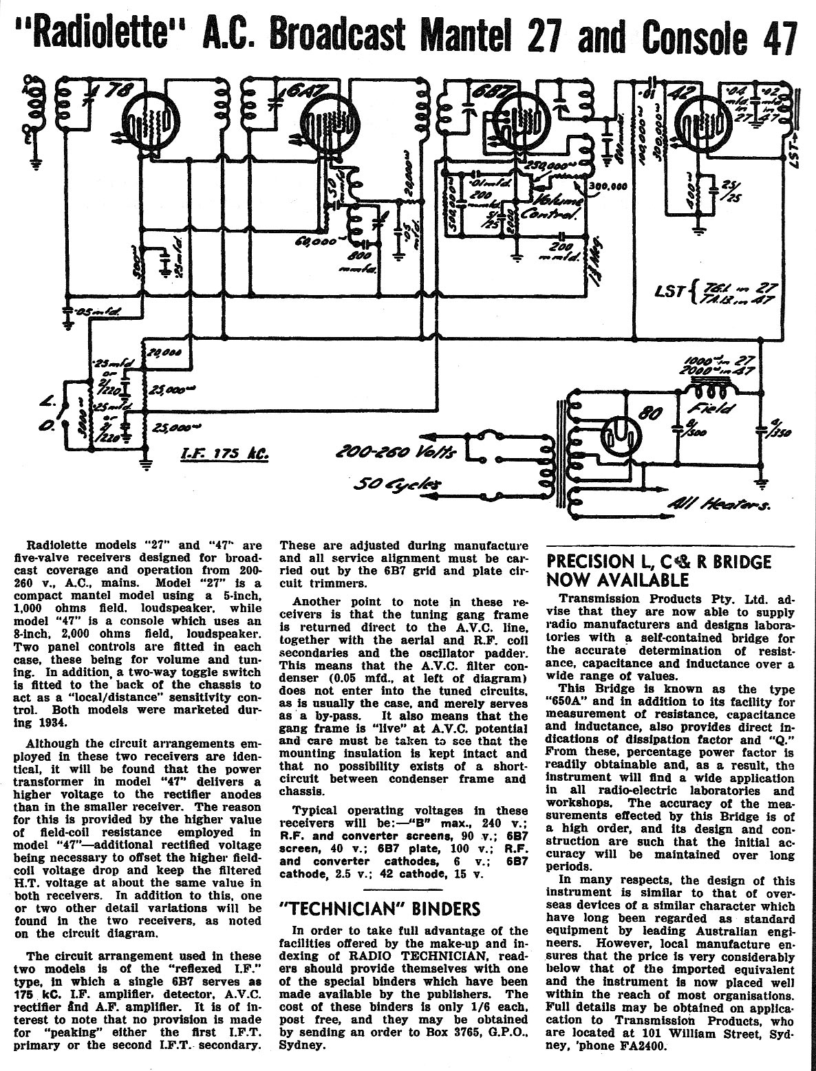 Please click image for higher resolution. |
|
|
Return to top of page · Post #: 7 · Written at 10:03:53 AM on 26 March 2010.
|
|
|
|
Administrator
Location: Naremburn, NSW
Member since 15 November 2005 Member #: 1 Postcount: 7624 |
|
Circuit diagram is uploaded. ‾‾‾‾‾‾‾‾‾‾‾‾‾‾‾‾‾‾‾‾‾‾‾‾‾‾‾‾‾‾‾‾‾‾‾‾‾‾‾‾‾‾‾‾‾‾‾‾‾‾‾‾‾‾‾‾‾‾‾‾‾‾‾‾‾‾‾‾ A valve a day keeps the transistor away... |
|
|
Return to top of page · Post #: 8 · Written at 5:10:22 PM on 6 May 2010.
|
|
|
|
Location: Balwyn, VIC
Member since 23 March 2010 Member #: 637 Postcount: 11 |
|
Marc and Brad, |
|
|
Return to top of page · Post #: 9 · Written at 5:42:57 PM on 6 May 2010.
|
|
|
|
Administrator
Location: Naremburn, NSW
Member since 15 November 2005 Member #: 1 Postcount: 7624 |
|
No worries about the time Peter. That is the beauty of forums - everything lasts forever. ‾‾‾‾‾‾‾‾‾‾‾‾‾‾‾‾‾‾‾‾‾‾‾‾‾‾‾‾‾‾‾‾‾‾‾‾‾‾‾‾‾‾‾‾‾‾‾‾‾‾‾‾‾‾‾‾‾‾‾‾‾‾‾‾‾‾‾‾ A valve a day keeps the transistor away... |
|
|
Return to top of page · Post #: 10 · Written at 8:44:25 PM on 2 June 2010.
|
|
|
|
Location: Balwyn, VIC
Member since 23 March 2010 Member #: 637 Postcount: 11 |
|
The speaker transformer is cactus. The identification printing is unreadable except for what looks like the word 'Rola', which doesn't surprise me. The circuit in an earlier post shows that the Model 27 should be a 'TG1' but there is no mention of input or output impedence. My memory suggests either 3000 or 5000 ohms, does anyone know what it should be? |
|
|
Return to top of page · Post #: 11 · Written at 9:35:33 PM on 2 June 2010.
|
|
|
|
Location: Wangaratta, VIC
Member since 21 February 2009 Member #: 438 Postcount: 5715 |
|
Use specifications for 6F6. |
|
|
« Back ·
1 ·
Next »
|
|
|
You need to be a member to post comments on this forum.
|
|

 250V Wo = 3.2 Watts
Sign In
Vintage Radio and Television is proudly brought to you by an era where things were built with pride and made to last.
DISCLAIMER: Valve radios and televisions contain voltages that can deliver lethal shocks. You should not attempt to work on a valve radio or other electrical appliances unless you know exactly what you are doing and have gained some experience with electronics and working around high voltages. The owner, administrators and staff of Vintage Radio & Television will accept no liability for any damage, injury or loss of life that comes as a result of your use or mis-use of information on this website. Please read our Safety Warning before using this website.
WARNING: Under no circumstances should you ever apply power to a vintage radio, television or other electrical appliance you have acquired without first having it checked and serviced by an experienced person. Also, at no time should any appliance be connected to an electricity supply if the power cord is damaged. If in doubt, do not apply power.
Shintara - Keepin' It Real · VileSilencer - Maintain The Rage