
Tech Talk
Forum home - Go back to Tech talk
|
Carbon pot characteristics & tap value for 1939 Hotpoint bandmaster 198DE
|
|
|
Return to top of page · Post #: 1 · Written at 8:10:27 PM on 5 April 2020.
|
|
|
|
Location: Riddells Creek, VIC
Member since 7 August 2009 Member #: 526 Postcount: 123 |
|
Hi all, curious to find out if anyone else has experienced a carbon type volume control changing its value over time...increasing in value. 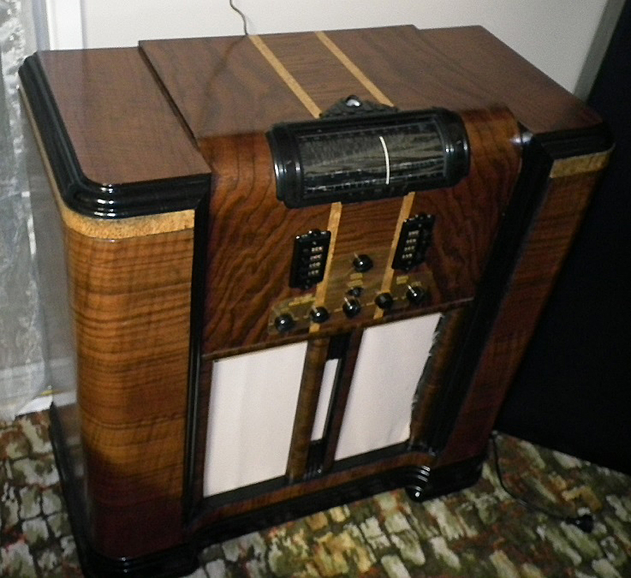 |
|
|
Return to top of page · Post #: 2 · Written at 8:48:00 PM on 5 April 2020.
|
|

|
Location: Sydney, NSW
Member since 28 January 2011 Member #: 823 Postcount: 6941 |
|
Sadly no value for the tap is specified so I’m not sure what to replace it with |
|
|
Return to top of page · Post #: 3 · Written at 11:09:05 AM on 6 April 2020.
|
|
|
|
Location: Riddells Creek, VIC
Member since 7 August 2009 Member #: 526 Postcount: 123 |
|
Thanks GTC, a look at the diagram....probably should have done that first! Shows you’re spot on...appears it’s tied into the music/speech switch. Sometimes a prod in the right direction is all that is needed! |
|
|
Return to top of page · Post #: 4 · Written at 7:34:01 PM on 7 April 2020.
|
|

|
Administrator
Location: Naremburn, NSW
Member since 15 November 2005 Member #: 1 Postcount: 7614 |
|
Photo uploaded. ‾‾‾‾‾‾‾‾‾‾‾‾‾‾‾‾‾‾‾‾‾‾‾‾‾‾‾‾‾‾‾‾‾‾‾‾‾‾‾‾‾‾‾‾‾‾‾‾‾‾‾‾‾‾‾‾‾‾‾‾‾‾‾‾‾‾‾‾ A valve a day keeps the transistor away... |
|
|
Return to top of page · Post #: 5 · Written at 9:52:19 AM on 8 April 2020.
|
|
|
|
Location: Riddells Creek, VIC
Member since 7 August 2009 Member #: 526 Postcount: 123 |
|
Just to update, thanks for uploading the pic Brad, ‘tis a beautiful looking unit which hopefully I can preserve in a working condition for future generations to enjoy. |
|
|
Return to top of page · Post #: 6 · Written at 5:36:22 PM on 16 April 2020.
|
|
|
|
Location: Melbourne, VIC
Member since 2 October 2019 Member #: 2392 Postcount: 284 |
|
Sorry for being completely off topic but Duconbuster can you tell me about what your profile pic is going on about? |
|
|
Return to top of page · Post #: 7 · Written at 8:49:48 AM on 25 April 2020.
|
|
|
|
Location: Riddells Creek, VIC
Member since 7 August 2009 Member #: 526 Postcount: 123 |
|
Hi there BurntOutElectronics, 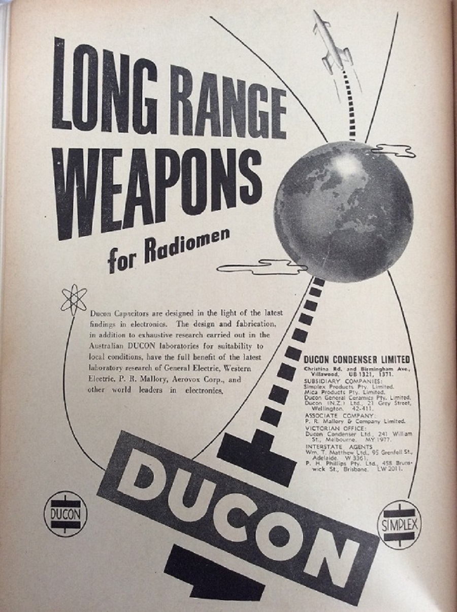 |
|
|
Return to top of page · Post #: 8 · Written at 4:36:11 PM on 25 April 2020.
|
|
|
|
Administrator
Location: Naremburn, NSW
Member since 15 November 2005 Member #: 1 Postcount: 7614 |
|
Photo uploaded to Post 7. ‾‾‾‾‾‾‾‾‾‾‾‾‾‾‾‾‾‾‾‾‾‾‾‾‾‾‾‾‾‾‾‾‾‾‾‾‾‾‾‾‾‾‾‾‾‾‾‾‾‾‾‾‾‾‾‾‾‾‾‾‾‾‾‾‾‾‾‾ A valve a day keeps the transistor away... |
|
|
Return to top of page · Post #: 9 · Written at 10:20:22 AM on 26 April 2020.
|
|
|
|
Location: Belrose, NSW
Member since 31 December 2015 Member #: 1844 Postcount: 2700 |
|
Yes, just as bad as all the other brands of paper capacitors!! |
|
|
Return to top of page · Post #: 10 · Written at 12:39:07 PM on 26 April 2020.
|
|
|
|
Location: Melbourne, VIC
Member since 2 October 2019 Member #: 2392 Postcount: 284 |
|
Yes their paper caps are total garbage but Ducon’s later plastic film caps and even some electrolytics are pretty good in my experience. Although I always change the electrolytic caps I like to test them and I find that later ducon electrolytics stand the test of time quite well, probably because of the addition of PCB’s as a stabiliser |
|
|
Return to top of page · Post #: 11 · Written at 7:41:06 PM on 26 April 2020.
|
|
|
|
Location: Belrose, NSW
Member since 31 December 2015 Member #: 1844 Postcount: 2700 |
|
For late 50s and later TVs with Ducon cans, I always attempt reforming if there is no sign of physical leakage. Never disappointed so far. |
|
|
Return to top of page · Post #: 12 · Written at 7:20:11 AM on 27 April 2020.
|
|
|
|
Location: Toongabbie, NSW
Member since 19 November 2015 Member #: 1828 Postcount: 1404 |
|
Agree with Ian about re-using Ducon electrolytic caps. |
|
|
Return to top of page · Post #: 13 · Written at 9:17:49 AM on 27 April 2020.
|
|
|
|
Location: Belrose, NSW
Member since 31 December 2015 Member #: 1844 Postcount: 2700 |
|
Yes Fred I pulled a chassis full of wax paper caps (mix of Ducon and UCC) from an AWA C209 TV chassis some years back. |
|
|
Return to top of page · Post #: 14 · Written at 4:51:23 PM on 27 April 2020.
|
|
|
|
Location: Melbourne, VIC
Member since 2 October 2019 Member #: 2392 Postcount: 284 |
|
I definitely don’t always replace old Ducon electrolytics, But I only keep them in my own gear and I always visually inspect them before trying to reform them. For instance the big filter Ducons in my Kriesler TV used in the power supply (two 100mfd at 200v) are in perfect shape! I monitored them when I first turned the TV on and I could barely feel any warmth and after a while they went stone cold again! Didn’t need to change one electro in that TV as they were all good ducons! |
|
|
Return to top of page · Post #: 15 · Written at 9:08:04 PM on 27 April 2020.
|
|
|
|
Administrator
Location: Naremburn, NSW
Member since 15 November 2005 Member #: 1 Postcount: 7614 |
|
Nothing mentioned in this thread so far will ever encourage me to leave old electrolytic or paper condensers in service. A Kriesler 11-20 almost brought the curtains down on my collecting future once due to an overheated power transformer caused by defective filter caps. I always replace them. For a few lousy dollars for replacements, there is no incentive to keep old ones in service and in some cases it is dangerous - just as dangerous as leaving a valve radio running without supervision, and I don't do that anymore either. ‾‾‾‾‾‾‾‾‾‾‾‾‾‾‾‾‾‾‾‾‾‾‾‾‾‾‾‾‾‾‾‾‾‾‾‾‾‾‾‾‾‾‾‾‾‾‾‾‾‾‾‾‾‾‾‾‾‾‾‾‾‾‾‾‾‾‾‾ A valve a day keeps the transistor away... |
|
|
You need to be a member to post comments on this forum.
|
|


Sign In
Vintage Radio and Television is proudly brought to you by an era where things were built with pride and made to last.
DISCLAIMER: Valve radios and televisions contain voltages that can deliver lethal shocks. You should not attempt to work on a valve radio or other electrical appliances unless you know exactly what you are doing and have gained some experience with electronics and working around high voltages. The owner, administrators and staff of Vintage Radio & Television will accept no liability for any damage, injury or loss of life that comes as a result of your use or mis-use of information on this website. Please read our Safety Warning before using this website.
WARNING: Under no circumstances should you ever apply power to a vintage radio, television or other electrical appliance you have acquired without first having it checked and serviced by an experienced person. Also, at no time should any appliance be connected to an electricity supply if the power cord is damaged. If in doubt, do not apply power.
Shintara - Keepin' It Real · VileSilencer - Maintain The Rage