Welcome to Australia's only Vintage Radio and Television discussion forums. You are not logged in. Please log in below, apply for an account or retrieve your password.
Australian Vintage Radio Forums
  Home  ·  About Us  ·  Discussion Forums  ·  Glossary  ·  Outside Links  ·  Policies  ·  Services Directory  ·  Safety Warnings  ·  Tutorials

Tech Talk

Forum home - Go back to Tech talk

 Tasma Console Radio model 1031
« Back · 1 · Next »
 Return to top of page · Post #: 1 · Written at 5:15:16 PM on 23 January 2020.
Normf's Gravatar
 Location: Cargo, NSW
 Member since 19 June 2018
 Member #: 2256
 Postcount: 96

Guessing it's a model 1031 as has 1031 stamped on back of chassis,
also has 1414 which may be the serial number.
Valve lineup 6J8 EBF35 6J7 6V6 5Y3.First 3 valves where in the wrong positions.
The EBF35 has a sticker on it's base with a ? on it.
O/P trany has o/c primary winding. 12" ED speakers appears to be OK.

Tasma 1031 Console Valve Radio


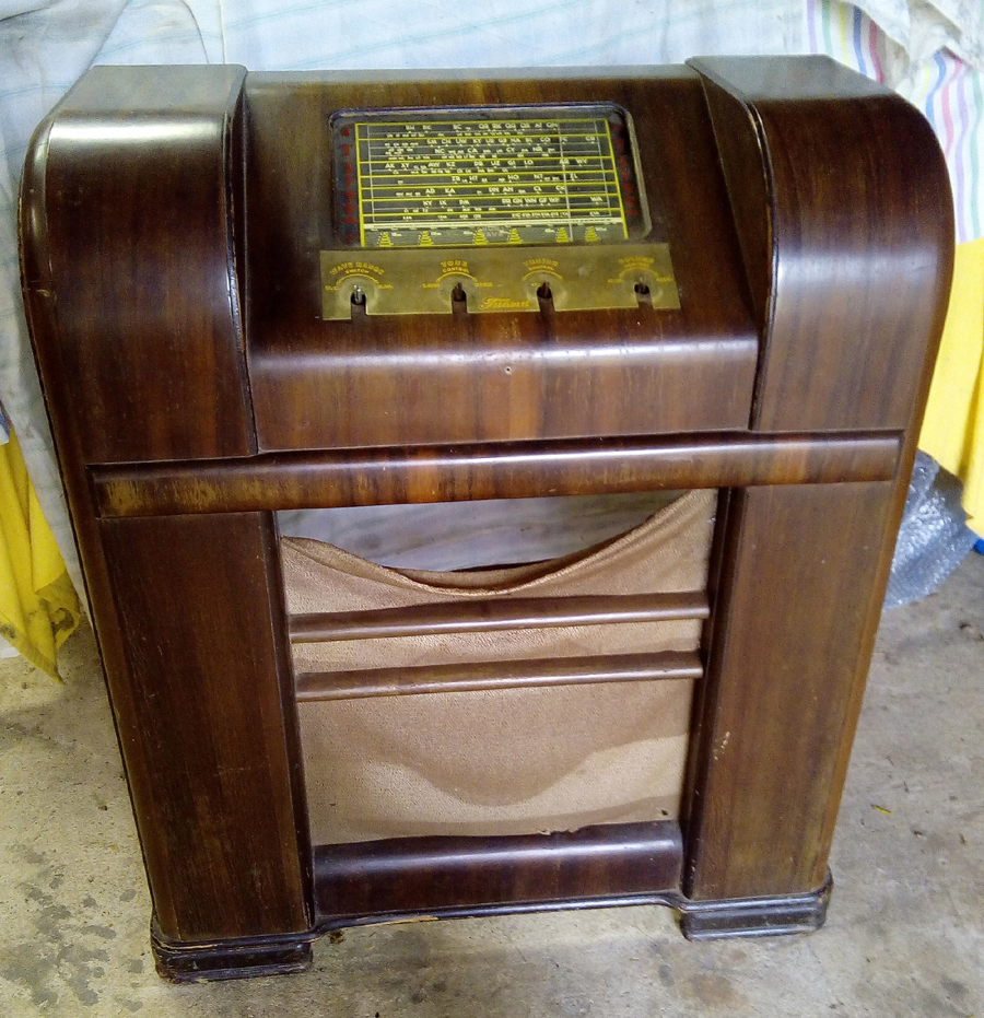
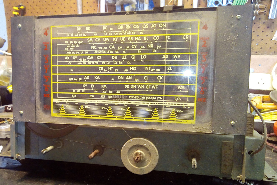
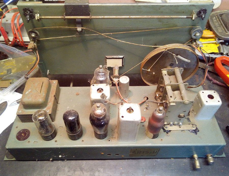
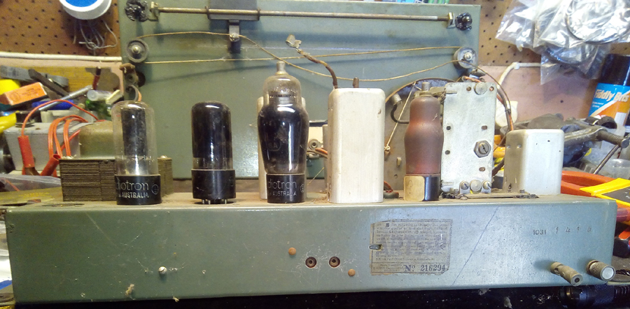
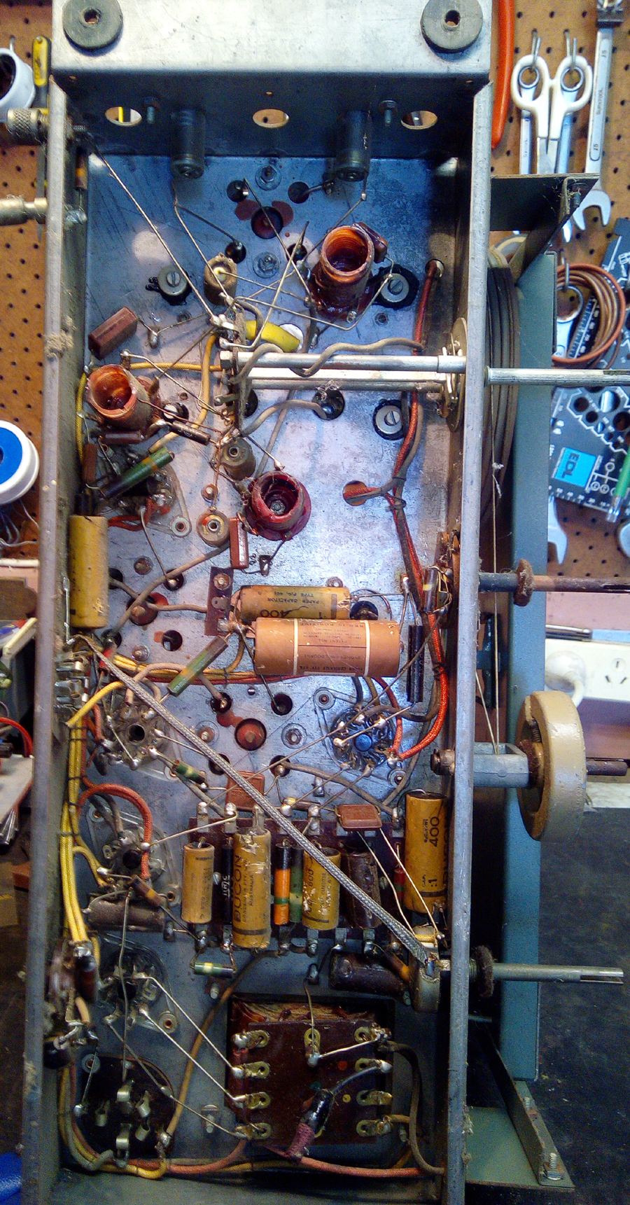
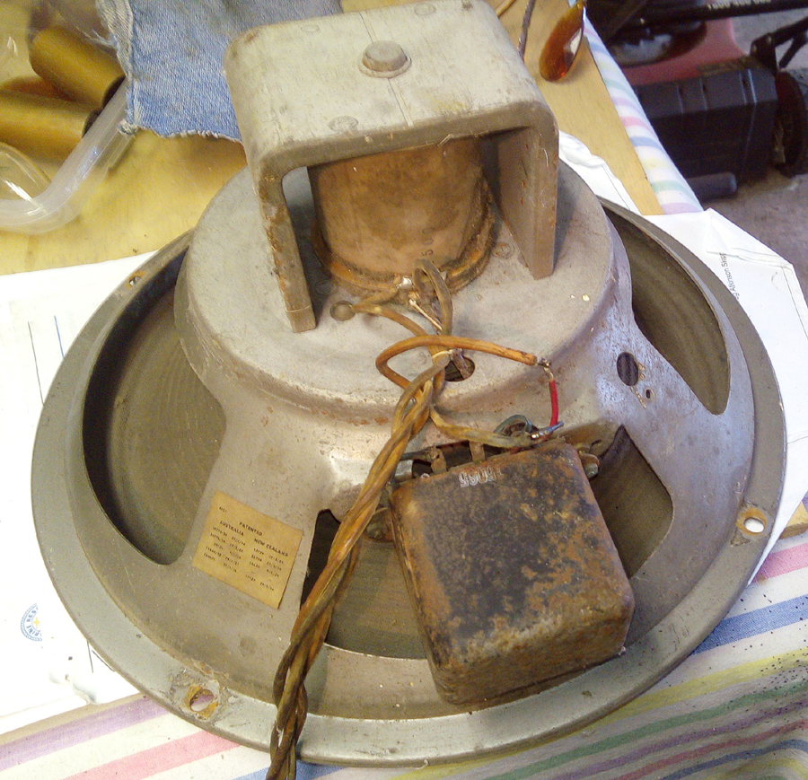
 Return to top of page · Post #: 2 · Written at 5:26:46 PM on 23 January 2020.
GTC's avatar
 GTC
 Location: Sydney, NSW
 Member since 28 January 2011
 Member #: 823
 Postcount: 6687

Model 1031 illustration and schematic on Radiomuseum.


 Return to top of page · Post #: 3 · Written at 8:39:50 PM on 23 January 2020.
Normf's Gravatar
 Location: Cargo, NSW
 Member since 19 June 2018
 Member #: 2256
 Postcount: 96

Looking at the wiring on the chassis the second valve would be a EBF32
not EBF2 as this is a type P socket not octal.

The EBF35 that is fitted is obviously not meant to be there.

The wiring fits an EBF32 but is different to that shown in the circuit.

The power transformer seems OK just doing an ohms test.

The pins in the valve sockets push out when a valve is inserted so may need to replace these.


 Return to top of page · Post #: 4 · Written at 11:47:23 PM on 23 January 2020.
Marcc's avatar
 Location: Wangaratta, VIC
 Member since 21 February 2009
 Member #: 438
 Postcount: 5254

EBF2G is the octal: It was superseded by EBF32 / EBF35

Beware: That does not have the common Philips pinout, nor the common octal. I have the circuit AORSM tatty. Someone was saving ink as two of the pentodes have the suppressor grid not drawn.

EBF2G and EBF35 have the same pinout. EBF32 does not: Pin one will be grounded.

EBF2 is a "P" Base.

I have had issues with Tasma's wire especially on heaters / filaments, Bad rubber & underrated wire.

circuit sent

Marc


 Return to top of page · Post #: 5 · Written at 7:30:18 PM on 24 January 2020.
Normf's Gravatar
 Location: Cargo, NSW
 Member since 19 June 2018
 Member #: 2256
 Postcount: 96

Thanks Marc received circuit from you OK.

Some of the wiring is brittle, but there is a major portion of the wiring laid out in a laced up wiring loom,
this appears to be a different type of wire and is not brittle.


 Return to top of page · Post #: 6 · Written at 7:49:08 PM on 3 February 2020.
Brad's avatar
 Administrator
 Location: Naremburn, NSW
 Member since 15 November 2005
 Member #: 1
 Postcount: 7302

Photos uploaded.


‾‾‾‾‾‾‾‾‾‾‾‾‾‾‾‾‾‾‾‾‾‾‾‾‾‾‾‾‾‾‾‾‾‾‾‾‾‾‾‾‾‾‾‾‾‾‾‾‾‾‾‾‾‾‾‾‾‾‾‾‾‾‾‾‾‾‾‾
A valve a day keeps the transistor away...

 
 Return to top of page · Post #: 7 · Written at 8:41:56 PM on 3 February 2020.
Robbbert's avatar
 Location: Hill Top, NSW
 Member since 18 September 2015
 Member #: 1801
 Postcount: 2015

Lots of untrustworthy parts in that radio.


 Return to top of page · Post #: 8 · Written at 10:03:48 PM on 3 February 2020.
Marcc's avatar
 Location: Wangaratta, VIC
 Member since 21 February 2009
 Member #: 438
 Postcount: 5254

OK! Lots of issues.

I would say that the fly leads are cactus. Whilst the operation may result in the crap rubber wire, they liked, cracking the covers may come off of those IF cans leaving the rest behind. You may need to leave the wire long to get it back through the hole or cut it the same or better length than the old & tack a snake wire to its end. If you use cloth coated then a bit of shrink tube on the end stops it fraying.

Note, or photo of the dial string on the drum & driver before you remove it & forget how it was.

If you do not touch or move the wire it may stay intact & circuit board lacquer can be a help. That whitish cap at the aerial coil may be electrolytic or an oil filled cap: Bin. Do check resistors as best as, when you change the caps. The 500K green black yellow band & 50K green black orange band have an attrition rate.

Beware with the highly strung rubber wire The string can cut into it causing the rubber to flake off & short.


Marc


 Return to top of page · Post #: 9 · Written at 1:07:48 PM on 4 February 2020.
Fred Lever's Gravatar
 Location: Toongabbie, NSW
 Member since 19 November 2015
 Member #: 1828
 Postcount: 1250

Hi Norm if you are stuck for a output tranny you can use a small power tranny in place.
I used a Jaycar MM2155 on my "vogue" restoration and bench tested that unit on a 6V6.

It worked fine with the laminations left interleaved or air gapped.
Made no difference at the magnetising level running the 6V6.
With a 8 ohm speaker using the 9 volt tap the reflected impedance back to the plate was around 5.5Kohm.
The 6V6 was a happy chappy on that.
Would be different at higher wattage levels and if you wanted 10hz to 20kHz response but for a radio its fine.
You can check the bench test its in my "vogue" article on this forum.

That set looks like a fine piece of gear, the underside looks like only time and the meece have been there, but not any monkeys!
What Marc said re wiring.
I would bet every wax and electro cap is leaky/shorted/open, and all those carbon resistors will be any value they feel like!
Cannot see the mains wiring, if its in that looming it would be scary and need cutting away and refreshing.

Let us know what you wind up having to replace, its interesting technically.

Fred.


 Return to top of page · Post #: 10 · Written at 9:21:23 PM on 4 February 2020.
Marcc's avatar
 Location: Wangaratta, VIC
 Member since 21 February 2009
 Member #: 438
 Postcount: 5254

I would suggest that the mains wire came out from underneath and its now a case of perhaps drilling a hole & shoving a gland in it, pointy end in to provide a compliant anchorage.

The holes in the speaker look like there may have been something in them? But do present a chance for a tag strip for new wire & anchorage. With some speaker plugs there can be issues if it is left out. That one looks OK but check to make sure if its out the screen of the 6v6 cannot get power. Many are wired so that it remains alive & it then becomes the plate and that, and an open transformer can destroy the screen.

Marc


 Return to top of page · Post #: 11 · Written at 6:55:55 AM on 5 February 2020.
Fred Lever's Gravatar
 Location: Toongabbie, NSW
 Member since 19 November 2015
 Member #: 1828
 Postcount: 1250

I was looking at the power transformer terminal plate trying to work out which terminal did what, yes I should get a life.

The power cord is that red braided stump cut short connected to the red dot primary.

Crikey...……. the HT side are those stiff bare wires that go straight to the 5Y3 and one via the speaker plug, that must be the filament and input to the choke. Eeeeeeeeeeeeeeek. What a finger trap for a killer shock!
I would be cutting all that stuff out and replacing with insulated wire with sleeving as much as possible.

I'll stop looking.

Fred.


 Return to top of page · Post #: 12 · Written at 9:48:25 AM on 5 February 2020.
Marcc's avatar
 Location: Wangaratta, VIC
 Member since 21 February 2009
 Member #: 438
 Postcount: 5254

A lot of "bread boards" & "coffin sets" were like that: Relapse. Problem with removing stuff is that it risks damage.

Marc


 Return to top of page · Post #: 13 · Written at 2:38:05 PM on 26 February 2020.
Normf's Gravatar
 Location: Cargo, NSW
 Member since 19 June 2018
 Member #: 2256
 Postcount: 96

Thanks for all your input
I cut off the mains cord,that's the red stump you can see at the power transformer.
The person who gave it to me said they tried to power it up but it blew the fuse so they cut a section of the end off the mains cord
and left it with the radio.
When I looked at the mains cord the rubber coating had perished in several places with the wires shorting out.
I always like to replace all electros and paper caps and test resistors as I go.
I take lots of photos of every part of the radio, and also as I am working on each section.
I don't like the look of those bare HT wires either, will replace them with insulated wire.
The layout diagram of above and below chassis, available from Radio Museum site shows the connections for the power transformer.
Have replaced one wire going to grid cap through the IF transformer, a good way to shield this wire going from volume control to grid of 6J7.
The rubber mounts for the tuning gang look like they have melted or become soft enough to run down the chassis, chassis is mounted at about a 60 degree angle.


« Back · 1 · Next »
 You need to be a member to post comments on this forum.

Sign In

Username:
Password:
 Keep me logged in.
Do not tick box on a computer with public access.