
Tech Talk
Forum home - Go back to Tech talk
|
Radio Identification
|
|
|
Return to top of page · Post #: 16 · Written at 10:44:11 PM on 22 January 2020.
|
|

|
Location: Hill Top, NSW
Member since 18 September 2015 Member #: 1801 Postcount: 2015 |
|
I noticed that the power transformer has a blob of wax on it, so it appears it has been overheating in the past. |
|
|
Return to top of page · Post #: 17 · Written at 11:33:59 PM on 22 January 2020.
|
|

|
Location: Wangaratta, VIC
Member since 21 February 2009 Member #: 438 Postcount: 5256 |
|
As mentioned I would not expect a grid stopper, or grid leak on a 6V6 to be in tolerance. Where there is a cathode bypass cap old & not used it can impinge on the bias & loading especially if it shorts, or is punched through by a failed open, cathode resistor. |
|
|
Return to top of page · Post #: 18 · Written at 6:55:29 PM on 24 January 2020.
|
|

|
Location: Nildottie, SA
Member since 7 April 2018 Member #: 2236 Postcount: 43 |
|
Replaced 220K and 220ohm. 500K reading 800K (the 30's resistor) but not sure of the Wattage. |
|
|
Return to top of page · Post #: 19 · Written at 7:31:11 PM on 24 January 2020.
|
|
|
|
Location: Toongabbie, NSW
Member since 19 November 2015 Member #: 1828 Postcount: 1251 |
|
Hi, Arcadus, the tolerance on the original electros was probably very wide. |
|
|
Return to top of page · Post #: 20 · Written at 8:30:07 PM on 24 January 2020.
|
|
|
|
Location: Wangaratta, VIC
Member since 21 February 2009 Member #: 438 Postcount: 5256 |
|
The first cap of a choke input filter where there is a 5Y3 / #80 should ape what was there and they are normally 535 peak volts. I normally use 600V. Increasing the value of that first cap will raise the voltage and that could be undesirable as it will also increase current draw. |
|
|
Return to top of page · Post #: 21 · Written at 8:48:33 PM on 25 January 2020.
|
|
|
|
Location: Nildottie, SA
Member since 7 April 2018 Member #: 2236 Postcount: 43 |
|
I will order the right caps then check the voltages again. 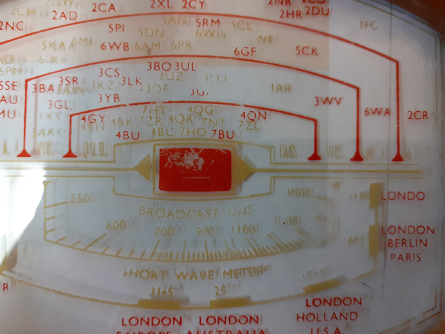 |
|
|
Return to top of page · Post #: 22 · Written at 10:55:43 PM on 25 January 2020.
|
|
|
|
Location: Wangaratta, VIC
Member since 21 February 2009 Member #: 438 Postcount: 5256 |
|
One should not have an issue with resistors. Just look at the place it is in the circuit, that is a basic, one needs to learn. The one in the bottom RH corner showing the black & green with an orange band is liable to be an out of spec 50K (they fail like crazy). The one under a 0.05 cap (top) with the green band is possibly AGC & 1Meg. |
|
|
Return to top of page · Post #: 23 · Written at 8:52:59 AM on 26 January 2020.
|
|
|
|
Location: Toongabbie, NSW
Member since 19 November 2015 Member #: 1828 Postcount: 1251 |
|
I played a game of "spot the resistor value" by colour. |
|
|
Return to top of page · Post #: 24 · Written at 9:13:40 AM on 26 January 2020.
|
|
|
|
Location: Belrose, NSW
Member since 31 December 2015 Member #: 1844 Postcount: 2372 |
|
Yes Fred, like you I can just look at a resistor and read its value without having to work it out. |
|
|
Return to top of page · Post #: 25 · Written at 10:26:46 AM on 29 January 2020.
|
|

|
Location: Werribee South, VIC
Member since 30 September 2016 Member #: 1981 Postcount: 470 |
|
After looking at resistors for 50 years I do the same. The only ones that require some thought are the 1% ones with the extra band. |
|
|
Return to top of page · Post #: 26 · Written at 10:44:44 AM on 29 January 2020.
|
|
|
|
Location: Nildottie, SA
Member since 7 April 2018 Member #: 2236 Postcount: 43 |
|
I assume the old black bodied (they are all black) resistors use the black as the second digit considering the first digit is represented as brown with the orange stripe being the multiplier as in the 10K. They must be decadic values not as modern resistors with variable second digits. |
|
|
Return to top of page · Post #: 27 · Written at 2:46:22 PM on 29 January 2020.
|
|
|
|
Location: Belrose, NSW
Member since 31 December 2015 Member #: 1844 Postcount: 2372 |
|
Yes. |
|
|
Return to top of page · Post #: 28 · Written at 5:12:33 PM on 29 January 2020.
|
|

|
Administrator
Location: Naremburn, NSW
Member since 15 November 2005 Member #: 1 Postcount: 7304 |
|
Photo uploaded to Post 21. ‾‾‾‾‾‾‾‾‾‾‾‾‾‾‾‾‾‾‾‾‾‾‾‾‾‾‾‾‾‾‾‾‾‾‾‾‾‾‾‾‾‾‾‾‾‾‾‾‾‾‾‾‾‾‾‾‾‾‾‾‾‾‾‾‾‾‾‾ A valve a day keeps the transistor away... |
|
|
Return to top of page · Post #: 29 · Written at 9:32:22 PM on 29 January 2020.
|
|
|
|
Location: Wangaratta, VIC
Member since 21 February 2009 Member #: 438 Postcount: 5256 |
|
330K may be the plate of the 2nd detector 1st Audio. Its probably a new one as they also fail like crazy (Somebody in the know was paying attention). Watch the 50K on the Pentagrid if its on a grid it actually may go to cathode not ground (Test it). More than 10% variance is liable to see it get the chop here. |
|
|
Return to top of page · Post #: 30 · Written at 8:08:54 PM on 30 January 2020.
|
|
|
|
Location: Linton, VIC
Member since 30 December 2016 Member #: 2028 Postcount: 467 |
|
Yikes---- |
|
|
You need to be a member to post comments on this forum.
|
|
Sign In
Vintage Radio and Television is proudly brought to you by an era where things were built with pride and made to last.
DISCLAIMER: Valve radios and televisions contain voltages that can deliver lethal shocks. You should not attempt to work on a valve radio or other electrical appliances unless you know exactly what you are doing and have gained some experience with electronics and working around high voltages. The owner, administrators and staff of Vintage Radio & Television will accept no liability for any damage, injury or loss of life that comes as a result of your use or mis-use of information on this website. Please read our Safety Warning before using this website.
WARNING: Under no circumstances should you ever apply power to a vintage radio, television or other electrical appliance you have acquired without first having it checked and serviced by an experienced person. Also, at no time should any appliance be connected to an electricity supply if the power cord is damaged. If in doubt, do not apply power.
Shintara - Keepin' It Real · VileSilencer - Maintain The Rage