Tech Talk Forum home - Go back to Tech talk
|
AM transistor mod to vary the received bandwidth depending on how strong or weak the station is. .
|
|
« Back ·
1 ·
Next »
|
|
|

|
Location: Oradell, US
Member since 2 April 2010
Member #: 643
Postcount: 839
|
AM transistor mod to vary the received bandwidth depending on how strong or weak the station is. Why, to get higher fidelity audio on the local stations, but avoiding "monkey chatter" from weak stations' adjacent stations.
Using a JFET as a voltage controlled resistor for variable IF bandwidth, and to act like an AVC circuit in a transistor AM radio. This circuit widens the bandwidth on strong stations (adjacent stations are so weak you wont hear them), for more audio high frequencies, better fidelity. Weak stations will have narrower passbands, avoiding "monkey chatter" from immediately adjacent weak stations.
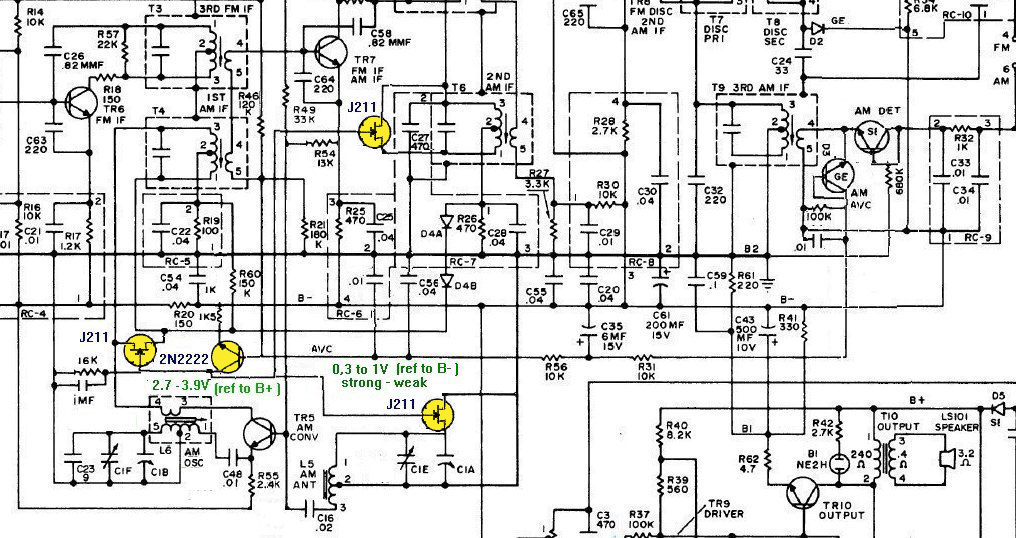
Here the usual AVC circuit in the AM section of this radio gets an assist from a JFET operating as a voltage controlled resistor. This is in the triode or ohmic region (at and near 0V and 0mA current, the blue region in the figure below) where the FET can operate as a voltage-controlled resistor. The triode or ohmic region in an FET is sometimes known as the linear region. The JFET operating as a voltage-controlled resistor works in this region. If we extend the VDS voltage range to include slightly negative voltages for a particular gate-t-source voltage, we see that the there is still a resistive effect. Preferably, there is no DC voltage across the JFET’s drain and source terminals in the voltage controlled resistance mode. This JFET's source and drain is connected across the entire LC circuit of the first IF transformer, which has no significant DC across it. The source and the drain both have IF frequency energy on them, out of phase with each other. The LC circuit has a tap near the center of the winding, tied to an RF ground (which is why the drain and source has out of phase IF energy) The gate is roughly at the midpoint of the resistance, which should reduce the effect of the gate capacitance on the IF.
When the gate voltage VGS here is dropped below around -4V, the JFET (a J211) becomes near infinite resistance. At around -2.7V, the JFET becomes a resistance around 1500 ohms. This variable resistance across the IF transformer LC circuit attenuates the signal strength, and also as a side benefit, will make that LC circuit have wider bandwidth. Which will allow higher audio frequencies from the strong station to be heard, higher fidelity (also better fidelity because the attenuation keeps the strong station from overdriving and distorting in the rest of the IF strip). Weaker stations will have narrower passbands, avoiding "monkey chatter" from immediately adjacent weak stations.
The controlling voltage is acquired from the AVC line via an inverting transistor (a 2N2222). This transistor level shifts and amplifies the AVC voltage range. Weak signals create a higher AVC voltage, and the transistor goes into more conductance, drawing, via the collector resistor, its collector voltage more negative. Strong signals will produce lower AVC voltages, and the transistor goes nearly into cutoff, and the collector approaches the positive supply rail. Be sure to use a bypass cap between this collector and the B+ line, to avoid ripple and such from "modulating" the voltage controlled resistances of the JFETs. Which would distort the detected audio. You need to size this cap to smooth out ripple, but still allow the circuit to respond to the AVC changing due to tuning in stations. I used a trimpot to get a sweet spot of an emitter resistor value, setting the gain of this transistor (a value that has the JFET do nothing on weak stations, but attenuates strong stations to minimise distortion), then I used a fixed resistor of this value in the finished circuit. Not a great way to do circuit design, as variations in the transistors and JFETs could throw this off in production. The IF transformer's LC circuit is also at the positive supply rail. From the JFET's point of view, (its gate is connected to the transistor collector) its gate going more negative makes the JFET resistance go higher. The gate getting less negative makes it lower resistance, attenuating the strong station's signal. As the AVC circuit is a feedback loop, the JFET's resistance will settle to a value after this loop does its action.
A second JFET on the IF transformer between the first and second IF stages is also installed. You don't want to put it at the last IF transformer, as all you'd do is attenuate distorted signal. A third JFET is also used on the antenna LC circuit (I removed a 1.5pF cap there, as the JFET has some internal capacitance, a few pF's, inside it). Then I retweaked the antenna trimmer cap.

Above shows an exaggerated relation of passbands (how wide some value of X dB down) to radio station signal strngths. The passbands really vary by a factor of two at most. Attenuation is related to AVC action, in that weak stations are amplified more than strong stations in regular AVC circuits, and here there is actual attenuation being done as well (which via the voltage controlled resistive JFETs changes the passband widths of the various IF transformers and the antenna LC circuit).
|
|
|
|
|
|
|
Location: Oradell, US
Member since 2 April 2010
Member #: 643
Postcount: 839
|
Another radio, this one AM, I did this mod on:
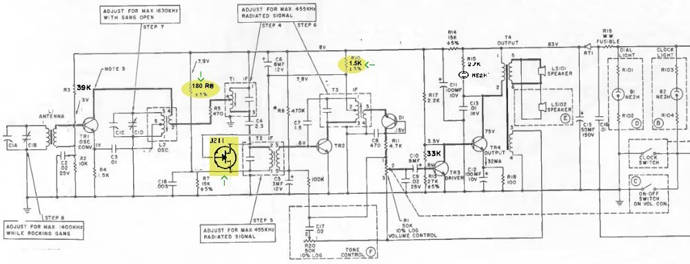
Here is a single JFET connected across the 2nd IF transformer T2. The IF amp transistor TR2 also acts like the 2N2222 in the radio in the original post above (as TR2's base gets biased by the AVC line), and the JFET control signal is picked off a bypassed resistor R10, was 1K, now 1.5K (to increase the control voltage range). The full LC circuit of T2 is bypassed by C18 and biased by voltage divider R6 and R7. There was a diode between T2 and R10, but I removed it before I added the JFET. The voltage divider was reworked (by changing R6 to 180 ohms) to have the JFET go almost into infinite resistance when the radio is tuned to an empty spot on the dial. And to drop resistance value on strong signals. This then widens the IF bandwidth and reduces the IF strip's gain.
|
|
|
|
|
|
Location: Silver City WI, US
Member since 10 May 2013
Member #: 1340
Postcount: 977
|
This is a great idea, worthy of a patent. Although it needs FETs, would still have been of benefit from 1960s onward, especially for car radios.
|
|
|
|
|

|
Location: Sydney, NSW
Member since 16 January 2008
Member #: 219
Postcount: 67
|
There were later AM/FM car radios that did that on AM, simply by switching in different bandwidth ceramic filters.
In fact I still have a Voxon AM stereo car radio with that feature.
I also vaguely remember an Electronic Australia project for adding that to existing radios with Murata 455kHz filters
The Jaycar AR1780 COMPACT WORLD BAND PLL RADIO WITH SSB allows you to select several different AM bandwidths as well as decoding it as a Quasi-SSB signal.
https://www.jaycar.com.au/compact-world-band-radio-with-ssb/p/AR1780
I've always thought you could do some interesting sound effects with an AM modulator and one of those.
I was thinking you could slightly change the carrier frequency of the modulator via a voltage from a musical keyboard, to make a poor man's vocoder 
|
|
|
|
|

|
Administrator
Location: Naremburn, NSW
Member since 15 November 2005
Member #: 1
Postcount: 7630
|
What we need is a way to do this to valve radios. 
‾‾‾‾‾‾‾‾‾‾‾‾‾‾‾‾‾‾‾‾‾‾‾‾‾‾‾‾‾‾‾‾‾‾‾‾‾‾‾‾‾‾‾‾‾‾‾‾‾‾‾‾‾‾‾‾‾‾‾‾‾‾‾‾‾‾‾‾
A valve a day keeps the transistor away...
|
|
|
|
|
|
|
Location: Oradell, US
Member since 2 April 2010
Member #: 643
Postcount: 839
|
Something I wrote up about 20 years ago: Using tubes as variable resistances (change the "plate resistance").

An interesting aspect of dual control pentodes is that the plate resistance increases in value as grid 3 is made more negative. This will load the output IF transformer's LC circuit less, causing its bandwidth to narrow. This will make for wider bandwidth on weak signals (and thus higher demodulated audio frequency response), as these signals will drive the AVC (and thus grid 3) less negative than strong stations would. But narrower bandwidth on strong signals. This is not a feature, as weak signals will be nosier, and lower audio frequency response would be desirable. Backwards to what I was hoping for.
One could add a triode plate to the primary of the IF transformer to variably load the transformer and thus vary its bandwidth. This mod assumes that the IF transformers are not overcoupled, as usually the case in AA5 radios. One would need the inverse of the usual AVC voltage to feed its grid. When one increases the current through the triode, its plate resistance decreases. We want a triode that has a rated plate resistance around 20 to 40K, like a 12AT7. We want that to happen on strong stations to get better high frequency audio fidelity. I used a zener to provide a constant bias for the cathode. Use a quiescent current resistor to keep the zener functioning when the triode passes very low current. So one needs a DC signal that gets more positive with more signal strength, so we can control the triode with it. One could get that using an infinite impedance detector instead of the usual detector diode. An interesting side effect of this triode circuit is that it also attenuates strong signals more than weak signals, thus helping the usual AVC circuit function. One has to be careful to balance things so it doesn't hog too much of this function. The diagram shows it hanging on the first IF primary, but an additional triode on the primary of the 2nd IF should also work if the detector is an infinite impedance type. The usual diode loads the 2nd IF enough such that a triode on that one wouldn't do much. That might even do enough AVC action so that the regular AVC circuit could be eliminated, but I haven't yet tried this. There may be unwanted feedback when using both triodes on a 12AT7 as both plates are not shielded from each other.
|
|
|
|
|

|
Location: Brunswick, VIC
Member since 3 May 2017
Member #: 2100
Postcount: 43
|
I tell you what this mod works a treat on my AWA Radiola Transistor 9.
Since the radio uses PNP germanium transistors I had to find a P channel JFET and needed an extra transistor for the AGC level shifting. The whole thing was built on a tiny piece of vero board that only needs 4 connections to the radio and no other modifications.
I was staggered with the change in performance. Before the bandwidth shrunk as the signal got stronger, I think because the first IF transistor that had the AGC applied to it was getting higher in output resistance as the gain was turned down. Now it stays clean and clear no matter what the signal strength is.
It is much better to listen to now. Mind you the sound quality still sounds like it is running through a Marshal Guitar amp that is being thrashed. The only thing that would fix that is a few vacuum tubes.
Regards, Frank.
|
|
|
|
|
|
|
Location: Oradell, US
Member since 2 April 2010
Member #: 643
Postcount: 839
|
Brad asked if this could be done with a valve radio. If you are okay with infecting a valve radio with solid state parts, then:
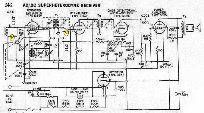
Some months ago I did some mods on solid state transistor radios, using JFETs as variable resistors across IF transformers. http://www.wa2ise.com/radios/amdettransistor.htm#6sb7z Idea is to use the AVC voltage to increase or decrease the JFET resistance to assist the AVC function, and to make received audio bandwidth on strong local stations wider. And perceived audio signal levels are more even while tuning across the AM band. Brad asked about doing this on tube sets. I put the JFET on the secondary of the 1st transformer. This secondary is riding on the AVC voltage line. For the JFET I used (J211), to have infinite resistance, its gate should be around -4V compared to its source and drain. About -2.7V gets about 1.5K resistance. Here, the source and drain (connected to the IF transformer secondary) are riding the AVC voltage, and I'd need a fixed negative voltage to connect the gate to. I used a half megohm trimpot on 12VAC (tapped the heater string) then rectified that and filtered it to get an adjustable negative bias for the gate. RF Bypass this bias to ground. I and added another JFET to the antenna circuit. JFETs add about 2pF of capacitance so you'll have to tweak the trimmers.
This radio is the classic All American 5ive hot chassis radio. This will work for transformer powered sets too.
|
|
|
|
« Back ·
1 ·
Next »
|
|
You need to be a member to post comments on this forum.
|

|
|
