Welcome to Australia's only Vintage Radio and Television discussion forums. You are not logged in. Please log in below, apply for an account or retrieve your password.
Australian Vintage Radio Forums
  Home  ·  About Us  ·  Discussion Forums  ·  Glossary  ·  Outside Links  ·  Policies  ·  Services Directory  ·  Safety Warnings  ·  Tutorials

Tech Talk

Forum home - Go back to Tech talk

 Pinnacle Porta possibly Model 2 Set #C401
« Back · 1 · Next »
 Return to top of page · Post #: 1 · Written at 4:43:26 PM on 14 August 2019.
Jime's Gravatar
 Location: Ashburton, VIC
 Member since 11 November 2015
 Member #: 1821
 Postcount: 8

I am currently looking at a partly restored Pinnacle Porta in order to identify its salient point for an Astor Book Revision.

Model 1 used A and B batteries only and UX199 valves. Tracing out the replaced wiring on chassis C401 seems to infer that the model 2 has a bias battery on the audio stages as well as a separate Low B+ for the detector and RF amplifier.
Again the valves appear to be UX199.

For the UX 199 detector a recommended maximum voltage for a grid leak configuration is 45 volts. For a separate grid bias on the audio stages would seem to indicate a higher B+ than 60V - possibly a maximum of 90V.

Re the Astor Porta and Pinnacle Porta sets there are more than one model of each. For the Astor Porta there were around ½ a dozen “models” using a variety of valves and styling. (UX199, A409s and B405)

Generally the Pinnacle Porta was recognised by its varnished oak case whereas the Astor Porta (or Astor 4 valve as it was initially called) has the blue/grey leatherette look

Does anyone have a Pinnacle Porta around the chassis number indicated to confirm or otherwise, the use of alternative batteries. I am interested in any Porta circuits other than the Ray Kelly one published in Radio Waves many years ago

Jime


 Return to top of page · Post #: 2 · Written at 8:54:11 PM on 14 August 2019.
Marcc's avatar
 Location: Wangaratta, VIC
 Member since 21 February 2009
 Member #: 438
 Postcount: 5254

It is / was a good idea even that it is probably wrong, to reverse engineer what you have. The plot of those was pretty much the same. The resultant circuit may then be helpful.

It may be that the sockets will be a clue. The pins on the Philips valves are likely European & UX is American & the pin is thicker. Pin spacing is not the same. Filament voltage of the B405 is 4 Volts and good for 150V with -18V bias 99 is only good for 90V.

99 Without bias as a detector 45V is the max, but these were often run at 22.5V. However, it can be run at 90V as a plate detector with around -10.5V grid bias to give a plate current of 0.2mA.

Marc


 Return to top of page · Post #: 3 · Written at 11:58:40 PM on 14 August 2019.
Jime's Gravatar
 Location: Ashburton, VIC
 Member since 11 November 2015
 Member #: 1821
 Postcount: 8

The Ray Kelly Astor Porta circuit had 60 V on the detector plate which seems high for an A409.

I wonder if the 60V B+ battery was actually tapped then drawn incorrectly.
My feeling is that at 60v HT self biasing would be adequate for the audio stages though any more HT and battery biasing would be required.

All of the sockets as stated in the original 1926 Pinnacle Porta "Tested by Us" article were UX based (as was C401).

For the Astor Portas the model changes could be picked by the speaker leads and output valves swapping from left to right sides repeatedly.

The dials also changed from Pilot Kilograd to Pilot fancy . Some had 3 A409s and a B405, some UX199, 2 X A409, B405.
The internal component positions changed as did the component models.

C401 used very early "Advance" Tuning capacitors, "Brunet" (not Power Plus) audio Transformers and a variable Gridleak 1/4 to 30 Meg.
Astor Portas were found with the later "Advance Little Centralign" Tuning Caps and a fixed 5 meg grid leak.

Otherwise the circuits appear similar.

I will get a copy of the circuit here soon when I read the instructions!

Jime


 Return to top of page · Post #: 4 · Written at 9:47:18 AM on 15 August 2019.
GTC's avatar
 GTC
 Location: Sydney, NSW
 Member since 28 January 2011
 Member #: 823
 Postcount: 6686

Is this the model you speak of? https://www.radiomuseum.org/r/astor_porta.html


 Return to top of page · Post #: 5 · Written at 3:35:12 PM on 15 August 2019.
Marcc's avatar
 Location: Wangaratta, VIC
 Member since 21 February 2009
 Member #: 438
 Postcount: 5254

That looks like a plausible combination 99 is a low 90V tube with a 3V filament all the rest will take 150V but the trap is 4V filaments, with appropriate bias, so there is a possibility of one of those multi tap "C" batteries?

I would be suspicious of the B Voltage as well. It depends on what battery's were made at the time 67.5V. I would believe, if they were the 22.5 /45V types, however, it is quite clear that with the correct bias even135V is feasible. 4V was likely 2 wet cells or part of a 6V, or rare at the time, 12V type (Outside connections then)

There may be a resistance in the filament circuit of 99. Reverse engineering and or comparison to one is getting more interesting.

Stability can be an issue in them if you have too many volts in the wrong place. Shielding was never flash in many, if any.

Marc


 Return to top of page · Post #: 6 · Written at 1:28:46 AM on 16 August 2019.
Jime's Gravatar
 Location: Ashburton, VIC
 Member since 11 November 2015
 Member #: 1821
 Postcount: 8

I have many advertisements of both Astor and Pinnacle Porta though only the one Ray Kelly Astor circuit plus the modified one I drew. The standard of workmanship of the earlier Pinnacle Porta is significantly different (poorer) than the Astor Porta. According to the Radiomuseum website the Pinnacle Manufacturing Company was in 573 Flinders Lane (Essex House) which I have verified was also Louis Coen Wireless. I will guess the Astor Porta was actually made by Radio Corporation Australia.

When Brad puts the circuits up soon, you will see the RF amp filament is controlled by one rheostat while the remaining valves filaments are operated off another rheostat. These were factory adjusted and could cater for 3 or 4 volt valves. The "volume" control as such was the regeneration control.The Model 1 Pinnacle and the later Astor versions all operated off 41/2 volt dry cells A supply and a 60v B battery. (I have an original Model 1 Pinnacle instruction sheet)

The Pinnacle Porta model started October 1926 and seems to have finished in May 1927.

The Astor Porta initially began as the Astor 4 valve in March 1927 (Louis Coen Catalogue) though wasn't advertised until about July 1927. An earlier speakerless version of the Astor 4 valve existed from late December 1926 to March 27.

I am after confirmation of whether model 2 Pinnacle Porta had amplifier battery biasing (rather than self biasing) and a separate possibly tapped B+ supply. The only set I have access to has been rewired so I cannot confirm the original wiring as the lead labels are missing. However we seem to be agreeing that a 60 v B+ on the detector appears to be too high.

Jime

Astor Porta
Astor Porta
Pinnacle Porta
Pinnacle Porta


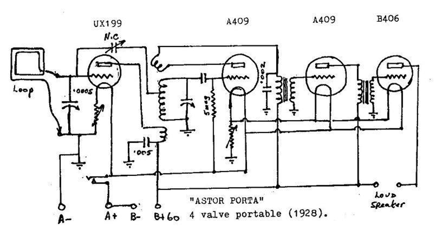
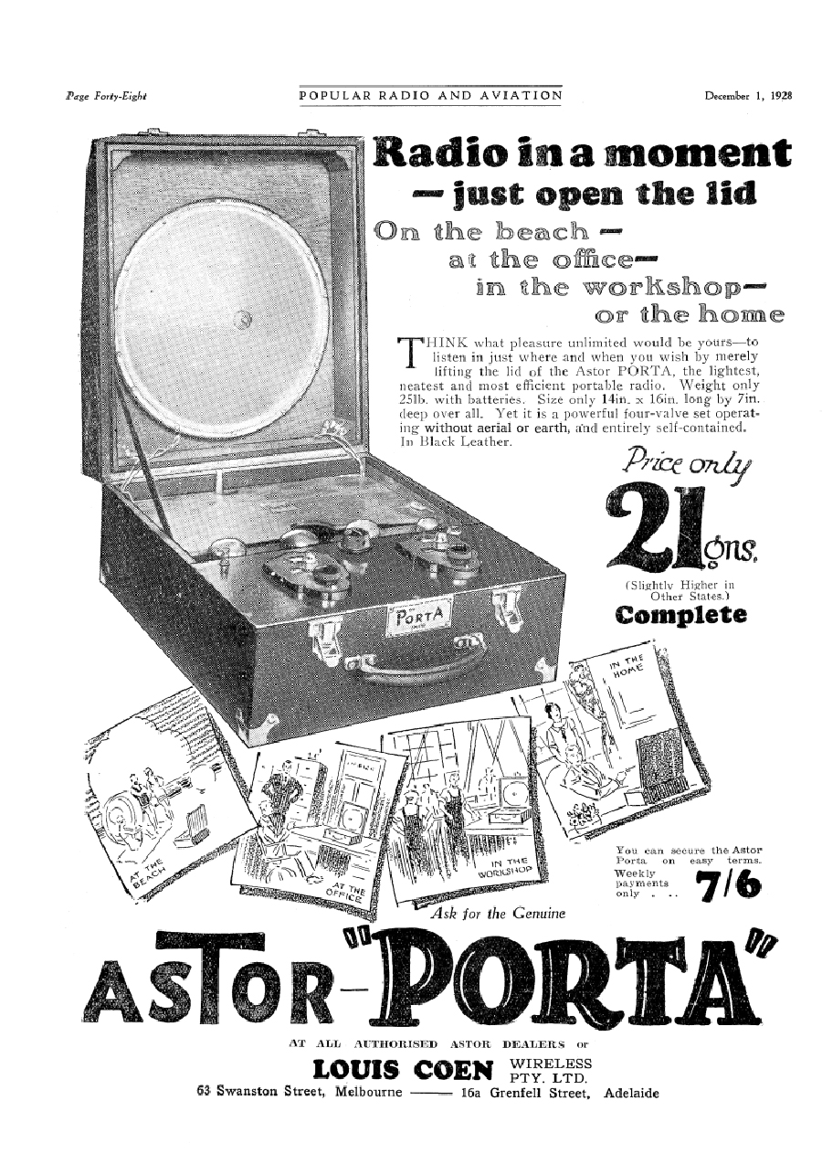
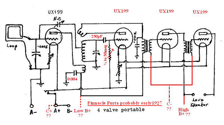
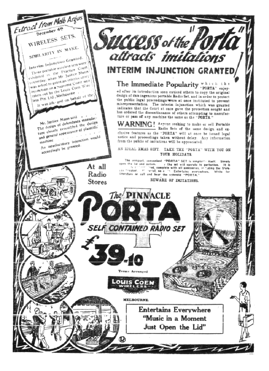
 Return to top of page · Post #: 7 · Written at 10:29:29 PM on 16 August 2019.
Brad's avatar
 Administrator
 Location: Naremburn, NSW
 Member since 15 November 2005
 Member #: 1
 Postcount: 7300

Photos uploaded to Post 6.

I'd never heard of Pinnacle until the other day when an early 1930s Pinnacle chassis was offered for sale on Ebay.


‾‾‾‾‾‾‾‾‾‾‾‾‾‾‾‾‾‾‾‾‾‾‾‾‾‾‾‾‾‾‾‾‾‾‾‾‾‾‾‾‾‾‾‾‾‾‾‾‾‾‾‾‾‾‾‾‾‾‾‾‾‾‾‾‾‾‾‾
A valve a day keeps the transistor away...

 
 Return to top of page · Post #: 8 · Written at 1:11:03 AM on 17 August 2019.
Jime's Gravatar
 Location: Ashburton, VIC
 Member since 11 November 2015
 Member #: 1821
 Postcount: 8

The Pinnacle Superhet stole the limelight at the 1925 Radio show claiming vague origins of London Paris Chicago rather than Flinders Lane Melbourne! The console was priced at 140 gns, Table model 100gns. Also featured was the Pinnacle TRF 5 and 6 (possibly Neutrodyne (unlicenced).These were the first Pinnacle sets. Louis Coen Wireless introduced the high end models just to announce the manufacturer. They were not equipped to go into production - so priced them outrageously.

The Pinnacle on ebay is 1935 despite other claims. I have the circuit. A brief look at the valve types 6A7, 6D6, 6B7, 43 and 25Z5 could not be before 1933 at the earliest. If you look at the back of the chassis its model PH. But I digress. Thanks for putting up the circuits Brad
Jime


 Return to top of page · Post #: 9 · Written at 9:45:42 AM on 17 August 2019.
Marcc's avatar
 Location: Wangaratta, VIC
 Member since 21 February 2009
 Member #: 438
 Postcount: 5254

One of the ways to not get caught with age, is to find out if possible (I have a list of some) as to when the valve's were actually released?

Do consider that the voltage drop across the filament is part of the bias. Do examine the way the detector is presented. I do wonder why (thinking aloud) its filament has a rheostat other than to get correct volts & perhaps a second volume? That is regenerative and the instant you change the filament volts, is the instant you change its operating parameters: That could well cause it to destabilise & may be why someone, who may not have fully understood it, was trying to control?

It is plausible to take the amplifier valves to their maximum of 90V however, that would need appropriate "C" bias. It was common to find cycle batteries (4.5V) in some of those sets. Perhaps the "B" is actually related to what they used for "C" ?

In the case of UX-201-A as an example. Once you exceed 45V as a detector it has to have "C" bias applied.

A lot can, in a lot of cases, be gleaned from the valve data sheets. I make a point of collecting some of the old data & was blessed when I went to sort out a set with UX-201-A's in it; when I found an RCA data sheet for them, with the exact circuit on it: One could not go wrong.

Marc


 Return to top of page · Post #: 10 · Written at 12:34:36 AM on 18 August 2019.
Jime's Gravatar
 Location: Ashburton, VIC
 Member since 11 November 2015
 Member #: 1821
 Postcount: 8

Thanks Marc you are quite correct about the biasing - it is there, though not obvious being the difference between the voltage the valves are set at minus the 4.5 volt battery supply. As it was common to underun the valves in the 20s battery sets there could easily be up to about a volt bias available. My gut feeling is that this is possibly about right at 60 volts.

The RF amp is neutralised and I believe it was the practice then for the RF valve to be underrun from it nominal voltage when setting the optimal neutralising capacitor position up.

The detector though is set up with a positive bias on the grid (going via the 5 meg from the positive filament). Usually this requires the detector plate to be low around 20 volts so I was a bit surprised to see a 45v maximum. Its this part I am struggling with. What am I missing for this to happen on the first diagram (the Ray Kelly one) at 60 volts.

Does anyone have the characteristic curves for the UX199? I can only find the setting for 90 v and a setting for one detector setting. Perhaps this would help me understand.

Jime


 Return to top of page · Post #: 11 · Written at 1:54:25 AM on 18 August 2019.
Marcc's avatar
 Location: Wangaratta, VIC
 Member since 21 February 2009
 Member #: 438
 Postcount: 5254

One cannot in most sets put positive on the grid. Having said that, if positive can make the grid hot enough it can become negative (RCA).

Lyric actually did the diode thing with a #24 in their 70 series, by tying the grid to the plate and using it as the rectifier (separate power supply) to provide a #50 with its -89V grid bias (Plate 450V)

Grid curves were not common early & may only appear in the specific Radiotron Data Manuals & design handbooks. Nomenclature was changed in 1930 C299 & CX99 became 99.

You may have the application data on Franks Electron tube pages; However there is a circuit & some data on Radio Museum.

I have a suspicion that buried in somewhere in my library of chaos, is a publication with a lot of tube curves.

Marc


 Return to top of page · Post #: 12 · Written at 11:48:13 AM on 20 August 2019.
Jime's Gravatar
 Location: Ashburton, VIC
 Member since 11 November 2015
 Member #: 1821
 Postcount: 8

Most of the early 20s gridleak detector circuits used positive bias on the grid return. For the reason the detector plate voltage was kept low often around 20 volts to stop the recommended plate current being exceeded.

To get the curves for the 99 valve it should be possible to utilise the curves for the 30 or 201A and restrict the curve to the range recommended for 99 as their characteristics in the range appear very similar.

Some juggling is required to get the curve for 60v. I will put my derived curve up tomorrow.

"Rectification" occurs in the grid leak detector circuits by operating in the bendy part of the characteristic curve.

Knowing this though doesn't seem to help as there are no characteristic curves for a positive grid voltage. What am I missing to understand?

Jime


 Return to top of page · Post #: 13 · Written at 3:17:16 PM on 20 August 2019.
Marcc's avatar
 Location: Wangaratta, VIC
 Member since 21 February 2009
 Member #: 438
 Postcount: 5254

As said should have data. You will note that for the leaky grid they do specify which side of the filament the grid is connected too: That is important, Anode bend is mentioned as a detector. The other way common in Autodynes pre valves with separate diodes involved either a "C" battery or in heater tubes a very high resistance cathode (self bias) to bias the valve to near cut off so that you had something like a plate current of 0.2mA.

I will have a look later, was doing some concrete work & the left ankle has now decided that it does not want to be involved in walking, or standing. Tractor & Motorcycle damage.


 Return to top of page · Post #: 14 · Written at 8:05:49 PM on 28 August 2019.
Jime's Gravatar
 Location: Ashburton, VIC
 Member since 11 November 2015
 Member #: 1821
 Postcount: 8

OK Re the B batteries in the 20's I have verified that these were multitapped affairs so I will guess that there was a 22.5 tap run separately for the detector rather than running it on 60 volts. So I think the first circuit drawn by Ray might be incorrect. My "guess" then is that the RF stage, 1st audio and output stage all operated on 60 volts while the detector was around 22.5 v.

Its a challenge to work these out when the set has been worked on and lead labels are missing. I think I have enough now to be more confident to try it out.

Jime


 Return to top of page · Post #: 15 · Written at 8:42:11 PM on 28 August 2019.
Marcc's avatar
 Location: Wangaratta, VIC
 Member since 21 February 2009
 Member #: 438
 Postcount: 5254

Most of the 45V batteries were tapped & the combinations progressed in steps of 22.5 V.

The "Leaky Grid" sometimes went to 45V however, that in some cases, with breadboards, could cause them to go into "supersonic" oscillation & that's hard to pick. As noted, the valve data and many circuits still survive. The transformers were normally around 3:1 and that was part of the voltage amplification.

You can draw the circuit & we can pick it to bits, or you can wire to a known circuit. As Mr Alexander never said: These feature simplesness; albeit there is not much that is "simple" about the way they work.

The valves prior to the detector can be run at their maximum provided that it does not result in overload of the detector. The value of the detector Grid leak resistor, does have a bearing on its sensitivity.

Same applies for the audio however, I would consider for the purpose of decoupling etc. that the first audio tube be run at a lesser voltage than the OP unless the circuit demands otherwise.

Do make sure that the polarity of the "A" battery (supply) is correct: Rheostat is normally in negative.

Marc


« Back · 1 · Next »
 You need to be a member to post comments on this forum.

Sign In

Username:
Password:
 Keep me logged in.
Do not tick box on a computer with public access.