Welcome to Australia's only Vintage Radio and Television discussion forums. You are not logged in. Please log in below, apply for an account or retrieve your password.
Australian Vintage Radio Forums
  Home  ·  About Us  ·  Discussion Forums  ·  Glossary  ·  Outside Links  ·  Policies  ·  Services Directory  ·  Safety Warnings  ·  Tutorials

Tech Talk

Forum home - Go back to Tech talk

 Raycophone 63AE - Beale Panchromatic
« Back · 1 · 2 · Next »
 Return to top of page · Post #: 1 · Written at 6:44:18 PM on 26 July 2019.
Nhanwell's Gravatar
 Location: Mount Lawley, WA
 Member since 12 September 2017
 Member #: 2167
 Postcount: 49

I acquired this set last week.

From the valve line up 58, 2A7, 58, 2B7, 2A5 & 80 and chassis number 63AE it appears to be a Raycophone chassis in a Beale Mistral cabinet. From 33/43 and probably made for the WA market - chassis is stamped 40 cycles.

There is an original Beale Panchromatic sticker on the top of the RF can.

The set is fitted with an early weston tuning indicator. Unfortunately only part of which has survived. I'm assuming it was some sort of shadow graph? Can anyone point me to any info on this indicator and were there any other Australian sets that used this?

Under the chassis there is evidence of several repairs (mmm thats a bit of a loose term).
Obviously the electrolytic s have been replaced by Ducon axial ones. There is a a black number on the red rubber at the end of the capacitors is this a date stamp? I can make out a 55 & 58 on them.

I haven't been able to find a schematic for the set but have traced out the circuit and had a go at drafting it up (photo to be attached).
I'm originally English and brought up with HT line at the top - just to explain my layout!

There has been some "tinkering" with the cathode bias resistors and possibly circuit. What I have drafted is what I think it should be!!
As found the cathode resistors of the 58 & 2A7 were tied back to the cathode of the 2B7 and not to chassis!

The 2B7 has a 75 Ohm cathode resistor much lower value than I got from the data sheet and what I see in similar lineups from that period.

The cathode resistor for the 58s is 500ohm.

Another oddity - but no sign of tampering - is in the anode circuit of the RF stage (58). I was expecting to find the coil in series with the HT to the anode. There is an RF choke in that position and a lead going off to the coil but no return path . Surely there would be little or no coupling to the next stage ? Or are there examples of this used elsewhere ? Or is it a bodge job?

Does anyone have either a 63AE in their collection or a circuit diagram so that I can sanity check mine?

From preliminary checks all coils, transformers are intact. I've no plans to start recapping or applying power until I'm happy That I understand the circuit.

All comments welcome.

Raycophone 63AE Valve Radio


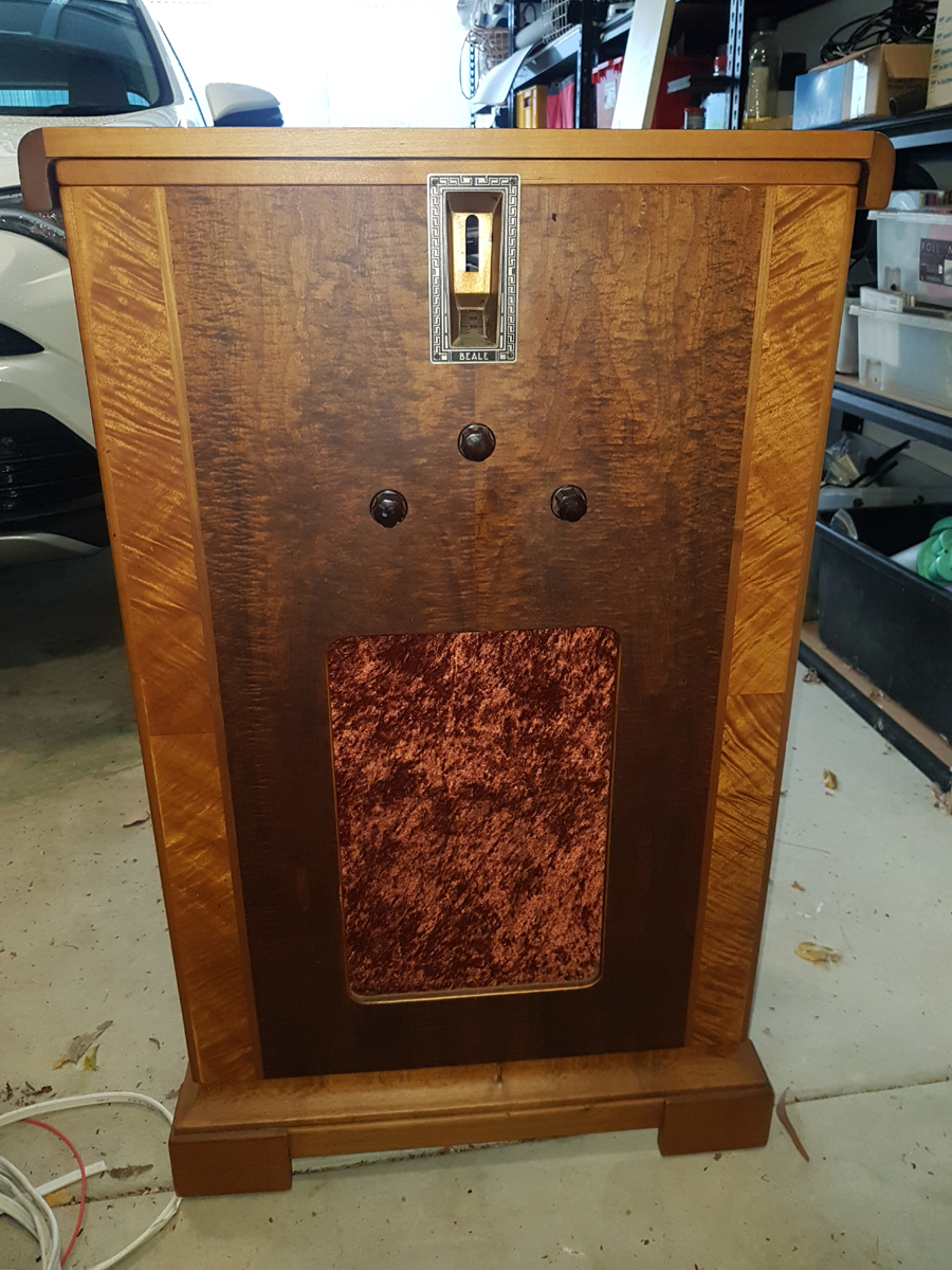
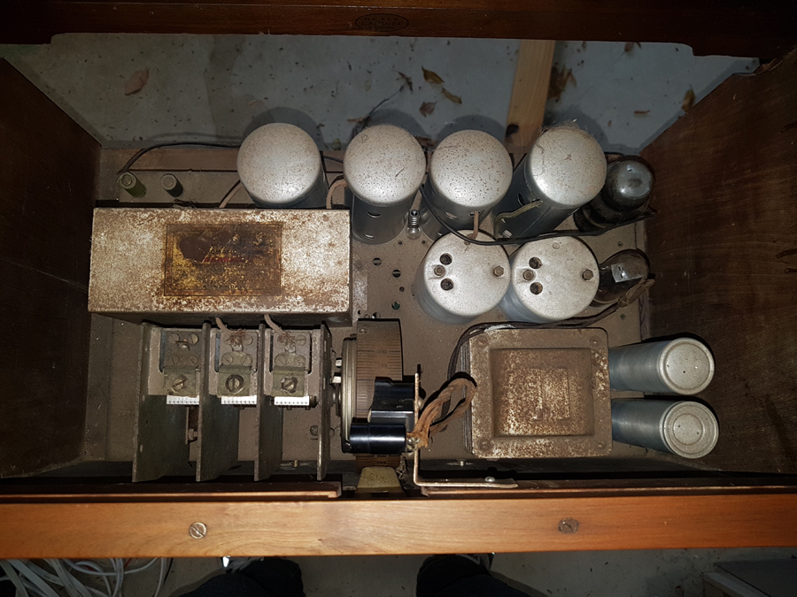
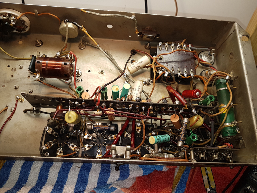
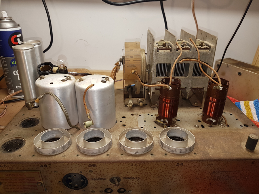
Raycophone 63AE Circuit Diagram


 Return to top of page · Post #: 2 · Written at 9:18:37 PM on 26 July 2019.
Marcc's avatar
 Location: Wangaratta, VIC
 Member since 21 February 2009
 Member #: 438
 Postcount: 5251

Where there is a TRF stage I have had one of those ? moments when it was realised that there was a choke in series with the plate & the varmint had gone open. It was I assure you not meant to couple.

My tactic is to use the AutoCAD to put the valves & transformers etc. in a layout as they are; Then play join the dots. AutoCAD is I think Win 98 but runs on XP so there is a computer just for it & searching the BU drive as it has the best search engine. The Program came with an electronics symbol library and others like plumbing.

There is a data sheet for 6B7 / 6B8 that shows the something like five ways you can wire it. There were instances of that circuit which were virtually unchanged as they moved to Octal. 58 became 6U7 with a base & heater change. 6A7 became 6A8: Base & heater change; 80 became 5Y3 with a base only change.2A7 became 6F6 with a heater & base change.

With the older sets the cathode of the Pentagrid & 1st IF were normally coupled to a potentiometer & that was the volume control.

I have seen some interesting hacks in some of them: Normally they failed, which is why several ended up here.

250V 40cps was common around WA in 1937.

Marc


 Return to top of page · Post #: 3 · Written at 9:46:39 PM on 26 July 2019.
STC830's Gravatar
 Location: NSW
 Member since 10 June 2010
 Member #: 681
 Postcount: 1256

There is a good article on tuning indicators in Radiomuseum:

https://www.radiomuseum.org/forum/history_of_tuning_indicators_meters_graphs_magic_eye_led.html

Also here

http://www.magiceyetubes.com/relatives.htm

Weston doesn't get a mention, but might of some help.


 Return to top of page · Post #: 4 · Written at 11:32:51 PM on 26 July 2019.
Marcc's avatar
 Location: Wangaratta, VIC
 Member since 21 February 2009
 Member #: 438
 Postcount: 5251

With the 6B7 fitted it is possibly a micro ammeter tied into some form of AGC. I think we await a circuit. There are likely explanations in some books I have here, as there are some written in that era. It is a good idea to keep an eye out for such things, should you want to understand how they work.

Knowing how things work is a great backgrounding. If you know how it works: Then you have an idea as to why it wont.


 Return to top of page · Post #: 5 · Written at 10:17:10 AM on 27 July 2019.
Nhanwell's Gravatar
 Location: Mount Lawley, WA
 Member since 12 September 2017
 Member #: 2167
 Postcount: 49

Thanks for your comments guys.
I'm assuming the tuning indicator was some sort of electro-mechanical shadow graph. Its (solenoid) coil was wired in series with the HT feed to the first IF transformer (2A5). As yet I haven't found any contemporary (Australian) sets that used one to confirm what it was actually and how it functioned.

I agree with Marc using a cad package and initially spotting the valves/coils/transformers makes the task of creating/tracing the circuit much easier. I also downloaded several schematics for sets with the same vale line up to see what was common practice.. that way I can take a closer look at areas that differ.

STC830 .. I've looked at the sites on tuning indicators but nothing so far that indicates what was used in this set. Here's hoping someone has a set with an intact indicator who can shed some light on it.

Agree totally Marc.. you can't fix something unless you understand how it should work.
That's why I thought I should highlight the two areas in the set that look a little "odd" to me (I've never seen that before - but my experience is limited) the anode circuit of the RF and the cathode bias of the the 58s & 2A5 going via the 2B7. It may ring bells with someone.

Hopefully, then it will be a straight forward exercise to get this little beauty running.

The cabinetry is in excellent condition with exception of missing fretwork over the speaker. It will make a nice piece to sit in the corner of the house.


 Return to top of page · Post #: 6 · Written at 10:51:07 AM on 27 July 2019.
Arty41's Gravatar
 Location: Brisbane, QLD
 Member since 18 September 2010
 Member #: 102
 Postcount: 301

Does your radio have a top that opens to expose the valves, I had one years ago, mine had a 1934 STC chassis in a Beale Panchromatic cabinet.


 Return to top of page · Post #: 7 · Written at 1:38:35 PM on 27 July 2019.
Nhanwell's Gravatar
 Location: Mount Lawley, WA
 Member since 12 September 2017
 Member #: 2167
 Postcount: 49

Hi Rudolf.
Yes the lid lifts up and I'd guess yours had an STC 67 chassis which has the same valve line up but may have had a few more knobs.


 Return to top of page · Post #: 8 · Written at 1:59:13 PM on 27 July 2019.
Arty41's Gravatar
 Location: Brisbane, QLD
 Member since 18 September 2010
 Member #: 102
 Postcount: 301

It's a long time since I had it, you're right mine would have had 2 or 3 knobs.


 Return to top of page · Post #: 9 · Written at 4:30:23 PM on 27 July 2019.
JFB's Gravatar
 JFB
 Location: Milton, NSW
 Member since 27 June 2016
 Member #: 1945
 Postcount: 55

Don't know about Weston but could the tuning indicator be a saturated reactor type? These typically have a lamp in series with a special form of iron cored inductance, in the plate circuit of an AVC controlled valve.

Details can be found in the Radio Designer's Handbook (my copy is 4th edition) by Langford-Smith page 1132 and undoubtedly many other places.

Just a thought - Joe


 Return to top of page · Post #: 10 · Written at 9:21:41 PM on 27 July 2019.
Brad's avatar
 Administrator
 Location: Naremburn, NSW
 Member since 15 November 2005
 Member #: 1
 Postcount: 7300

The lid is a definite Beale giveaway - there were a couple of Beale-badged radios with that top. If your Raycophone is anything like mine it will weigh as much as a tank. They were well made and Raycophone should have been in business far longer than they were.


‾‾‾‾‾‾‾‾‾‾‾‾‾‾‾‾‾‾‾‾‾‾‾‾‾‾‾‾‾‾‾‾‾‾‾‾‾‾‾‾‾‾‾‾‾‾‾‾‾‾‾‾‾‾‾‾‾‾‾‾‾‾‾‾‾‾‾‾
A valve a day keeps the transistor away...

 
 Return to top of page · Post #: 11 · Written at 11:04:56 AM on 28 July 2019.
Nhanwell's Gravatar
 Location: Mount Lawley, WA
 Member since 12 September 2017
 Member #: 2167
 Postcount: 49

Thanks Brad.
She is certainly well constructed and heavy!

Joe - what is left of the tuning indicator is visible in picture 3 .. a dial lamp that is supplied direct from heater chain and a coil that was (I think) in series) with HT to primary IFT1. What this did or moved - I don't know. Doesn't look like a saturated reactor type.

Other unknown in circuit is shown in picture 3 - rotary switch which has been disconnected - looks like it was connected to volume control by shielded wire. Could this have been a basic tone control circuit switching a capacitor in/out circuit to give a treble cut ? I've been looking at contemporary circuits but haven't seen anything similar .. so hopeful the brains trust may have some ideas or seen similar.

I've attached a circuit diagram in JPG form for upload which hopefully will help with discussion.

Thanks guys


 Return to top of page · Post #: 12 · Written at 2:29:23 PM on 28 July 2019.
Gandhn's Gravatar
 Location: Cameron Park, NSW
 Member since 5 November 2010
 Member #: 770
 Postcount: 387

My guess at the operation of the tuning indicator is.......

The coil is a simple solenoid with the armature movement proportional to anode current, which is directly proportional to AVC voltage which is directly proportional to signal strength.
The armature probably connects to a flexible cord to rotate the circular part against some spring tension and this part appears to have a window at the bottom. The lamp shines through this window, shining a beam on the front screen and this beam moves L to R or R to L in accordance with signal strength.

How's that for a theory.

Harold


 Return to top of page · Post #: 13 · Written at 10:07:05 PM on 28 July 2019.
Brad's avatar
 Administrator
 Location: Naremburn, NSW
 Member since 15 November 2005
 Member #: 1
 Postcount: 7300

My apologies for forgetting the link to the circuit diagram. The link to this is now below the photos. In accordance with recent tradition, I have converted this to a PDF so members can enlarge it for easier reading.


‾‾‾‾‾‾‾‾‾‾‾‾‾‾‾‾‾‾‾‾‾‾‾‾‾‾‾‾‾‾‾‾‾‾‾‾‾‾‾‾‾‾‾‾‾‾‾‾‾‾‾‾‾‾‾‾‾‾‾‾‾‾‾‾‾‾‾‾
A valve a day keeps the transistor away...

 
 Return to top of page · Post #: 14 · Written at 11:18:47 PM on 28 July 2019.
Marcc's avatar
 Location: Wangaratta, VIC
 Member since 21 February 2009
 Member #: 438
 Postcount: 5251

Ok! Whist looking for info on a cable oscillator, I found reference to the Indicators. In days of old we had no AGC. We had the “Grid Leak” and then the Plate detector. In the grid leak type on the arrival of a signal the Plate current in a Grid leak falls. With the “Plate detector: aka Anode bend it rides. Therefore, a sensitive current meter in the Plate circuit, or in the case of the latter, a neon tube, can be used to indicate the best tuning.

Where there is AGC /AVC an anode can still be used, but most likely that in an IF tube with AGC applied to it. As the AGC voltage grows stronger, that will see its voltage impinge on the grid and the Anode current fall, as the grid becomes more negative.

There were quite a few US sets that used analogue tuning meters.

Those UCC caps need checking: If they have not got "Polyester" on them they may well be paper types?

The wet caps should be disconnected and not left in circuit. Bulk should not be hard to sort: Wet afternoon job. There is a message re top tuner IF coils before you touch.

Marc


 Return to top of page · Post #: 15 · Written at 6:35:50 PM on 10 August 2019.
Ian Robertson's Gravatar
 Location: Belrose, NSW
 Member since 31 December 2015
 Member #: 1844
 Postcount: 2369

Yes well spotted Marc. Those white UCCs are indeed paper ("Hi_Qual" = paper, "DiPol" = polyester).

Those wet can caps will be very dry by now and are often S/C. I'd hide new electros inside them. But that may be exactly what has already been done, I can't see them anywhere else.

Good luck!


« Back · 1 · 2 · Next »
 You need to be a member to post comments on this forum.

Sign In

Username:
Password:
 Keep me logged in.
Do not tick box on a computer with public access.