
Tech Talk
Forum home - Go back to Tech talk
|
11-98 transformer
|
|
|
Return to top of page · Post #: 61 · Written at 12:20:29 PM on 3 September 2024.
|
|
|
|
Location: Newcastle, NSW
Member since 6 June 2020 Member #: 2422 Postcount: 20 |
|
Success!!! |
|
|
Return to top of page · Post #: 62 · Written at 3:00:37 PM on 3 September 2024.
|
|
|
|
Location: Cameron Park, NSW
Member since 5 November 2010 Member #: 770 Postcount: 428 |
|
Great that you found the problem, it was a long way from the first thought of a power transformer fault. |
|
|
Return to top of page · Post #: 63 · Written at 9:54:41 AM on 16 September 2024.
|
|
|
|
Location: Newcastle, NSW
Member since 6 June 2020 Member #: 2422 Postcount: 20 |
|
Harold yes. I can see my old electronics instructor tapping me on the head for such a back to front way around. |
|
|
Return to top of page · Post #: 64 · Written at 12:20:10 PM on 16 September 2024.
|
|

|
Location: Sydney, NSW
Member since 28 January 2011 Member #: 823 Postcount: 6963 |
|
It looks to me that J1 and J2 are not normal jacks because of the switching function. |
|
|
Return to top of page · Post #: 65 · Written at 9:48:06 AM on 17 September 2024.
|
|

|
Location: Wangaratta, VIC
Member since 21 February 2009 Member #: 438 Postcount: 5730 |
|
With stereo's it is often unwise to tamper with the working amp if there is one found faulty. The working one becomes the reference, even down to the point of current draw. |
|
|
Return to top of page · Post #: 66 · Written at 2:04:17 PM on 17 September 2024.
|
|
|
|
Location: Cameron Park, NSW
Member since 5 November 2010 Member #: 770 Postcount: 428 |
|
If R30 is over heating and the voltage at the junction of R30 and R27 is low (as previously indicated), you have a power supply problem. I suggest you temporarily forget all the other problems and fix this first. |
|
|
Return to top of page · Post #: 67 · Written at 9:34:53 AM on 19 September 2024.
|
|
|
|
Location: Newcastle, NSW
Member since 6 June 2020 Member #: 2422 Postcount: 20 |
|
So, 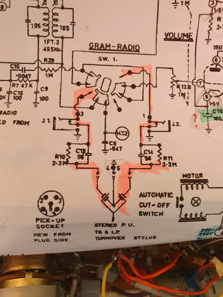 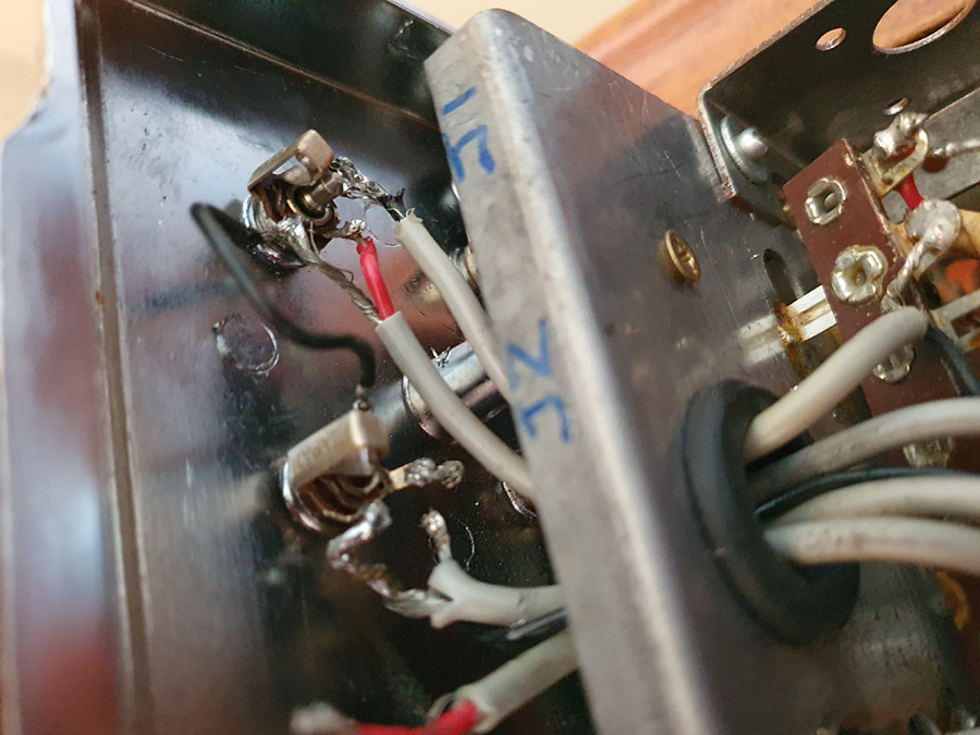 |
|
|
Return to top of page · Post #: 68 · Written at 11:40:28 AM on 19 September 2024.
|
|
|
|
Location: Cameron Park, NSW
Member since 5 November 2010 Member #: 770 Postcount: 428 |
|
SW 1 is shown in the Radio position. The Gram position is a rotation anti clockwise, connecting the top contact of J2 to the volume control R12B. |
|
|
Return to top of page · Post #: 69 · Written at 5:30:46 AM on 20 September 2024.
|
|

|
Administrator
Location: Naremburn, NSW
Member since 15 November 2005 Member #: 1 Postcount: 7643 |
|
Photos uploaded to Post 67. ‾‾‾‾‾‾‾‾‾‾‾‾‾‾‾‾‾‾‾‾‾‾‾‾‾‾‾‾‾‾‾‾‾‾‾‾‾‾‾‾‾‾‾‾‾‾‾‾‾‾‾‾‾‾‾‾‾‾‾‾‾‾‾‾‾‾‾‾ A valve a day keeps the transistor away... |
|
|
Return to top of page · Post #: 70 · Written at 12:33:02 PM on 20 September 2024.
|
|
|
|
Location: Wangaratta, VIC
Member since 21 February 2009 Member #: 438 Postcount: 5730 |
|
I am smelling a rat here. I would surmise that no photo's were taken of the switch to show where the wires were: Before they were put where they weren't. |
|
|
You need to be a member to post comments on this forum.
|
|
Sign In
Vintage Radio and Television is proudly brought to you by an era where things were built with pride and made to last.
DISCLAIMER: Valve radios and televisions contain voltages that can deliver lethal shocks. You should not attempt to work on a valve radio or other electrical appliances unless you know exactly what you are doing and have gained some experience with electronics and working around high voltages. The owner, administrators and staff of Vintage Radio & Television will accept no liability for any damage, injury or loss of life that comes as a result of your use or mis-use of information on this website. Please read our Safety Warning before using this website.
WARNING: Under no circumstances should you ever apply power to a vintage radio, television or other electrical appliance you have acquired without first having it checked and serviced by an experienced person. Also, at no time should any appliance be connected to an electricity supply if the power cord is damaged. If in doubt, do not apply power.
Shintara - Keepin' It Real · VileSilencer - Maintain The Rage