
Tech Talk
Forum home - Go back to Tech talk
|
Kit set i need I.D on.
|
|
|
Return to top of page · Post #: 61 · Written at 10:29:44 AM on 22 April 2023.
|
|

|
Location: Wangaratta, VIC
Member since 21 February 2009 Member #: 438 Postcount: 5715 |
|
Something like an Astor JJ is reflexed. |
|
|
Return to top of page · Post #: 62 · Written at 11:24:01 PM on 27 April 2023.
|
|

|
Administrator
Location: Naremburn, NSW
Member since 15 November 2005 Member #: 1 Postcount: 7624 |
|
Circuit diagram uploaded to Post 60. ‾‾‾‾‾‾‾‾‾‾‾‾‾‾‾‾‾‾‾‾‾‾‾‾‾‾‾‾‾‾‾‾‾‾‾‾‾‾‾‾‾‾‾‾‾‾‾‾‾‾‾‾‾‾‾‾‾‾‾‾‾‾‾‾‾‾‾‾ A valve a day keeps the transistor away... |
|
|
Return to top of page · Post #: 63 · Written at 7:19:22 AM on 28 April 2023.
|
|

|
Location: Latham, ACT
Member since 21 February 2015 Member #: 1705 Postcount: 2230 |
|
Hey thanks Fred and Brad. I have some progress photos ready to send . I will try and send this afternoon |
|
|
Return to top of page · Post #: 64 · Written at 9:37:22 AM on 28 April 2023.
|
|
|
|
Location: Wangaratta, VIC
Member since 21 February 2009 Member #: 438 Postcount: 5715 |
|
6K8 drawing is technically incorrect. it is a Triode Hexode. |
|
|
Return to top of page · Post #: 65 · Written at 11:20:48 AM on 28 April 2023.
|
|
|
|
Location: Toongabbie, NSW
Member since 19 November 2015 Member #: 1828 Postcount: 1407 |
|
Hi Carl some more photos and confirmation of the number of IF's will help. 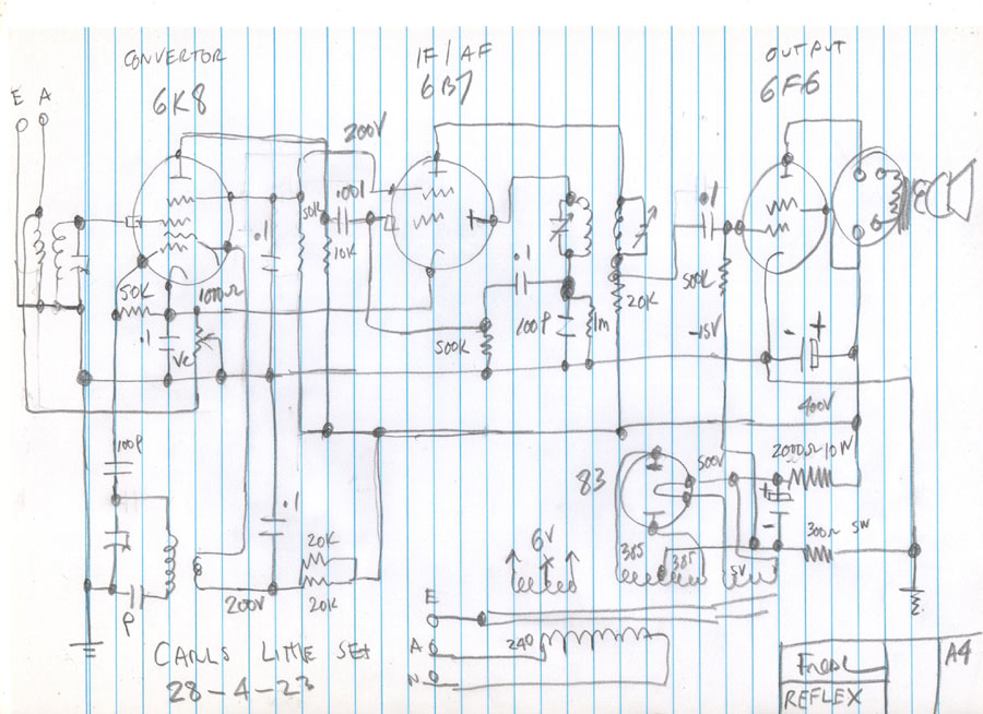 |
|
|
Return to top of page · Post #: 66 · Written at 11:58:37 AM on 28 April 2023.
|
|
|
|
Location: Latham, ACT
Member since 21 February 2015 Member #: 1705 Postcount: 2230 |
|
Ok Fred. |
|
|
Return to top of page · Post #: 67 · Written at 2:14:15 PM on 28 April 2023.
|
|

|
Location: Hill Top, NSW
Member since 18 September 2015 Member #: 1801 Postcount: 2254 |
|
I wondered about that diagram. It shows the earth terminal not going directly to earth, but instead being connected to the volume? control. |
|
|
Return to top of page · Post #: 68 · Written at 2:55:25 PM on 28 April 2023.
|
|
|
|
Location: Wangaratta, VIC
Member since 21 February 2009 Member #: 438 Postcount: 5715 |
|
I have always said, that irrespective of how you go about it, reverse engineering is a painful process. The first drawing is the layout diagram the second or lastly the wiring diagram. |
|
|
Return to top of page · Post #: 69 · Written at 8:00:31 PM on 28 April 2023.
|
|
|
|
Location: Toongabbie, NSW
Member since 19 November 2015 Member #: 1828 Postcount: 1407 |
|
Yeh Rob, the first SCETCH got the volume control a bit wrong. |
|
|
Return to top of page · Post #: 70 · Written at 9:21:03 PM on 28 April 2023.
|
|
|
|
Location: Hill Top, NSW
Member since 18 September 2015 Member #: 1801 Postcount: 2254 |
|
Yes, I've seen that arrangement in a few of my sets. It's ok-ish, until the control gets noisy. Then things turn nasty. |
|
|
Return to top of page · Post #: 71 · Written at 10:06:35 PM on 28 April 2023.
|
|
|
|
Location: Latham, ACT
Member since 21 February 2015 Member #: 1705 Postcount: 2230 |
|
Fred it only has one IFT. I have sent Brad some more photos. 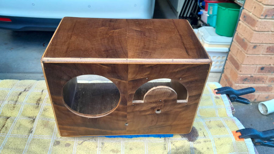 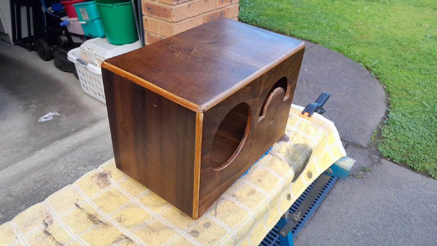  |
|
|
Return to top of page · Post #: 72 · Written at 11:35:37 PM on 28 April 2023.
|
|
|
|
Location: Wangaratta, VIC
Member since 21 February 2009 Member #: 438 Postcount: 5715 |
|
I am sending Brad & Carl an example of where the AutoCAD starts out. It will put in other caps & resistances and draw the wiring in colour. 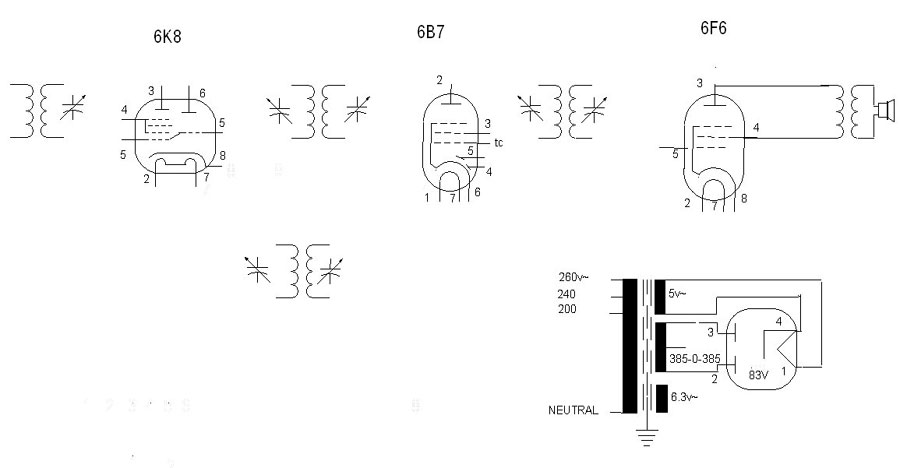 |
|
|
Return to top of page · Post #: 73 · Written at 4:43:57 AM on 30 April 2023.
|
|
|
|
Administrator
Location: Naremburn, NSW
Member since 15 November 2005 Member #: 1 Postcount: 7624 |
|
Photos uploaded to Posts 65, 71 & 72. ‾‾‾‾‾‾‾‾‾‾‾‾‾‾‾‾‾‾‾‾‾‾‾‾‾‾‾‾‾‾‾‾‾‾‾‾‾‾‾‾‾‾‾‾‾‾‾‾‾‾‾‾‾‾‾‾‾‾‾‾‾‾‾‾‾‾‾‾ A valve a day keeps the transistor away... |
|
|
Return to top of page · Post #: 74 · Written at 8:41:00 AM on 30 April 2023.
|
|
|
|
Location: Toongabbie, NSW
Member since 19 November 2015 Member #: 1828 Postcount: 1407 |
|
Carl, that cabinet scrubbed up well! |
|
|
Return to top of page · Post #: 75 · Written at 10:22:06 AM on 30 April 2023.
|
|
|
|
Location: Wangaratta, VIC
Member since 21 February 2009 Member #: 438 Postcount: 5715 |
|
The thing to note is that with the AutoCAD you can shift things if the space needs amending. That's why the oscillator coil is below the Frequency changer: Lots do that & it can get messy if you have a muti band Autodyne Colpitts oscillator as the exciter. |
|
|
You need to be a member to post comments on this forum.
|
|
Sign In
Vintage Radio and Television is proudly brought to you by an era where things were built with pride and made to last.
DISCLAIMER: Valve radios and televisions contain voltages that can deliver lethal shocks. You should not attempt to work on a valve radio or other electrical appliances unless you know exactly what you are doing and have gained some experience with electronics and working around high voltages. The owner, administrators and staff of Vintage Radio & Television will accept no liability for any damage, injury or loss of life that comes as a result of your use or mis-use of information on this website. Please read our Safety Warning before using this website.
WARNING: Under no circumstances should you ever apply power to a vintage radio, television or other electrical appliance you have acquired without first having it checked and serviced by an experienced person. Also, at no time should any appliance be connected to an electricity supply if the power cord is damaged. If in doubt, do not apply power.
Shintara - Keepin' It Real · VileSilencer - Maintain The Rage