
Tech Talk
Forum home - Go back to Tech talk
|
Electrola Cocktail Bar Radiogram
|
|
|
Return to top of page · Post #: 46 · Written at 4:51:56 PM on 21 February 2024.
|
|
|
|
Location: TUMBI UMBI, NSW
Member since 14 November 2022 Member #: 2525 Postcount: 42 |
|
Hi all, I've been busy and finally getting back to this project. I'm struggling to know for sure if I'm reading this colour code correctly as I am finding different answers on various sites while googling for the correct information. Unfortunately there is no circuit diagram available to check with. Could any of you more experienced please let me know the correct way to read it ? I will send a picture of the resistor to the webmaster in a moment. 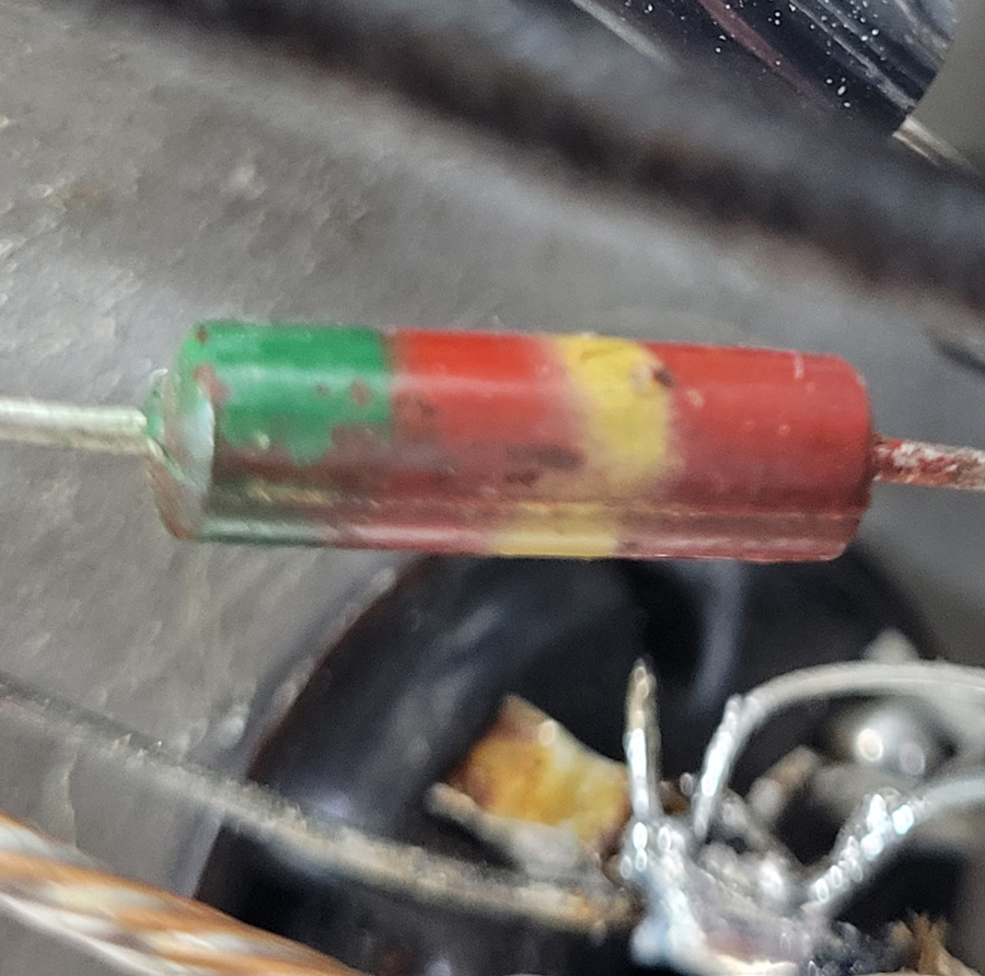 |
|
|
Return to top of page · Post #: 47 · Written at 6:55:58 PM on 21 February 2024.
|
|
|
|
Location: Belrose, NSW
Member since 31 December 2015 Member #: 1844 Postcount: 2699 |
|
Those resistors use the Body - End - Band system. They read as follows: |
|
|
Return to top of page · Post #: 48 · Written at 9:41:15 PM on 21 February 2024.
|
|
|
|
Location: TUMBI UMBI, NSW
Member since 14 November 2022 Member #: 2525 Postcount: 42 |
|
|
|
|
Return to top of page · Post #: 49 · Written at 10:33:02 PM on 21 February 2024.
|
|

|
Administrator
Location: Naremburn, NSW
Member since 15 November 2005 Member #: 1 Postcount: 7614 |
|
Photo uploaded to Post 46. ‾‾‾‾‾‾‾‾‾‾‾‾‾‾‾‾‾‾‾‾‾‾‾‾‾‾‾‾‾‾‾‾‾‾‾‾‾‾‾‾‾‾‾‾‾‾‾‾‾‾‾‾‾‾‾‾‾‾‾‾‾‾‾‾‾‾‾‾ A valve a day keeps the transistor away... |
|
|
Return to top of page · Post #: 50 · Written at 10:48:49 PM on 21 February 2024.
|
|

|
Location: Hill Top, NSW
Member since 18 September 2015 Member #: 1801 Postcount: 2249 |
|
250K ohms - often used as the anode load resistor on the audio triode. A 220k or 270k will do fine as a replacement. |
|
|
Return to top of page · Post #: 51 · Written at 11:45:20 PM on 21 February 2024.
|
|

|
Location: Wangaratta, VIC
Member since 21 February 2009 Member #: 438 Postcount: 5696 |
|
I would check that with an ohm meter There is no brown the paint has fallen off I have one with pretty much the some colour its marked 0.25 meg and is no longer in the radio as its 295.3K. |
|
|
Return to top of page · Post #: 52 · Written at 7:42:15 AM on 22 February 2024.
|
|
|
|
Location: TUMBI UMBI, NSW
Member since 14 November 2022 Member #: 2525 Postcount: 42 |
|
Thanks for your replies. That resistor comes off 6M5 output tube, plate pin 7 and goes to another which looks like same value but is larger and that resistor goes to pin 3 of the 6N8. There another different value resistor connected to the junction between the two resistors. |
|
|
Return to top of page · Post #: 53 · Written at 7:44:24 PM on 22 February 2024.
|
|
|
|
Location: Belrose, NSW
Member since 31 December 2015 Member #: 1844 Postcount: 2699 |
|
That 250 k resistor is a half watt. |
|
|
Return to top of page · Post #: 54 · Written at 9:12:25 PM on 22 February 2024.
|
|
|
|
Location: TUMBI UMBI, NSW
Member since 14 November 2022 Member #: 2525 Postcount: 42 |
|
The resistor in the picture measures at 300K. The other that I mentioned measure at 215K. I also mentioned another resistor off the same junction, it is blue orange blue green 65K? It measure at 100K. |
|
|
Return to top of page · Post #: 55 · Written at 10:15:29 PM on 22 February 2024.
|
|
|
|
Location: Wangaratta, VIC
Member since 21 February 2009 Member #: 438 Postcount: 5696 |
|
That does not sound right. B+ Wires & resistances wandering off to other places will not be on the plate Pin 7 Only the speaker transformer should be on that with perhaps a capacitor. |
|
|
Return to top of page · Post #: 56 · Written at 6:57:02 AM on 23 February 2024.
|
|
|
|
Location: Toongabbie, NSW
Member since 19 November 2015 Member #: 1828 Postcount: 1404 |
|
I don't know the set or the circuit, but a high value resistor hooked to the output valve plate is seen occasionally. |
|
|
Return to top of page · Post #: 57 · Written at 10:18:09 AM on 23 February 2024.
|
|
|
|
Location: Wangaratta, VIC
Member since 21 February 2009 Member #: 438 Postcount: 5696 |
|
It sounds like a weird circuit as pin 3 of a horrid little 6N8 is its cathode. Very rare to see a cathode follower arrangement for feedback. Grid 2 is pin1 6N8. Pin one 6N8 & pin one 6M5 I can see linked to B+ and high value resistors cutting the power to a 6N8, as detector 1st AF. |
|
|
Return to top of page · Post #: 58 · Written at 1:56:26 PM on 23 February 2024.
|
|
|
|
Location: TUMBI UMBI, NSW
Member since 14 November 2022 Member #: 2525 Postcount: 42 |
|
I also thought this to be weird as I'm using a couple other circuits with the same valve line up as a reference. Strangely enough it actually works albeit for only a short period. The bias voltage just keeps increasing to way above from what I understand it should be. I posted that comment to see if the far more experienced had come across this before. I think someone has make this error at some time. I will now check out the circuit against what info I have to try and work it out. |
|
|
Return to top of page · Post #: 59 · Written at 5:50:15 PM on 23 February 2024.
|
|
|
|
Location: TUMBI UMBI, NSW
Member since 14 November 2022 Member #: 2525 Postcount: 42 |
|
Sorry I made a mistake. Pin 6 of the 6N8 not pin 3 as I earlier typed. My apologies for the error. |
|
|
Return to top of page · Post #: 60 · Written at 2:08:08 AM on 24 February 2024.
|
|
|
|
Location: Wangaratta, VIC
Member since 21 February 2009 Member #: 438 Postcount: 5696 |
|
Voltage on the control grid pin2 6M5 is governed by the cathode resistor and how hard they want to drive it it will be in the order of 140 to 170 Ohms and if things are right the voltage across Rk will be the grid voltage. Has it actually got a cathode resistor? That may have a bearing on why it grinds to a halt. |
|
|
You need to be a member to post comments on this forum.
|
|
Sign In
Vintage Radio and Television is proudly brought to you by an era where things were built with pride and made to last.
DISCLAIMER: Valve radios and televisions contain voltages that can deliver lethal shocks. You should not attempt to work on a valve radio or other electrical appliances unless you know exactly what you are doing and have gained some experience with electronics and working around high voltages. The owner, administrators and staff of Vintage Radio & Television will accept no liability for any damage, injury or loss of life that comes as a result of your use or mis-use of information on this website. Please read our Safety Warning before using this website.
WARNING: Under no circumstances should you ever apply power to a vintage radio, television or other electrical appliance you have acquired without first having it checked and serviced by an experienced person. Also, at no time should any appliance be connected to an electricity supply if the power cord is damaged. If in doubt, do not apply power.
Shintara - Keepin' It Real · VileSilencer - Maintain The Rage