
Tech Talk
Forum home - Go back to Tech talk
|
Old Electrolytics
|
|
|
Return to top of page · Post #: 31 · Written at 1:37:04 PM on 31 October 2013.
|
|
|
|
Location: Somewhere, USA
Member since 22 October 2013 Member #: 1437 Postcount: 896 |
|
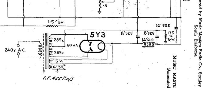
Is it the negatives of the two 8MFD that are supposed to be connected to ground via the 175 resistor, and the negative of the 16MFD cap connected directly to ground? |
|
|
Return to top of page · Post #: 32 · Written at 1:51:57 PM on 31 October 2013.
|
|
|
|
Location: Somewhere, USA
Member since 22 October 2013 Member #: 1437 Postcount: 896 |
|
This clearly shows, on the left hand side, |
|
|
Return to top of page · Post #: 33 · Written at 2:45:38 PM on 31 October 2013.
|
|
|
|
Location: NSW
Member since 10 June 2010 Member #: 681 Postcount: 1379 |
|
Electrolytics used for high tension filtering are usually connected in a pi arrangement with the caps as the "legs" and a choke (speaker field coil or separate choke) or a high wattage wire-wound resistor as the "lid". Negative to chassis. |
|
|
Return to top of page · Post #: 34 · Written at 2:59:39 PM on 31 October 2013.
|
|
|
|
Location: Somewhere, USA
Member since 22 October 2013 Member #: 1437 Postcount: 896 |
|
Here's the schematic: |
|
|
Return to top of page · Post #: 35 · Written at 3:13:14 PM on 31 October 2013.
|
|
|
|
Location: NSW
Member since 10 June 2010 Member #: 681 Postcount: 1379 |
|
Re schematic: I could make out the connection points, but not much help if there was a stuff up in original assembly or subsequent servicing. |
|
|
Return to top of page · Post #: 36 · Written at 3:50:17 PM on 31 October 2013.
|
|
|
|
Location: Somewhere, USA
Member since 22 October 2013 Member #: 1437 Postcount: 896 |
|
You mean a stuffed cap? |
|
|
Return to top of page · Post #: 37 · Written at 3:59:56 PM on 31 October 2013.
|
|
|
|
Location: NSW
Member since 10 June 2010 Member #: 681 Postcount: 1379 |
|
Sorry , meant stuff up! |
|
|
Return to top of page · Post #: 38 · Written at 4:05:44 PM on 31 October 2013.
|
|
|
|
Location: Somewhere, USA
Member since 22 October 2013 Member #: 1437 Postcount: 896 |
|
I think stuff up in original assembly. |
|
|
Return to top of page · Post #: 39 · Written at 4:24:28 PM on 31 October 2013.
|
|
|
|
Location: NSW
Member since 10 June 2010 Member #: 681 Postcount: 1379 |
|
Assembly errors and undocumented factory circuit changes are not unknown. |
|
|
Return to top of page · Post #: 40 · Written at 12:26:32 AM on 1 November 2013.
|
|
|
|
Location: Somewhere, USA
Member since 22 October 2013 Member #: 1437 Postcount: 896 |
|
That was bad |
|
|
Return to top of page · Post #: 41 · Written at 10:03:36 AM on 1 November 2013.
|
|
|
|
Location: NSW
Member since 10 June 2010 Member #: 681 Postcount: 1379 |
|
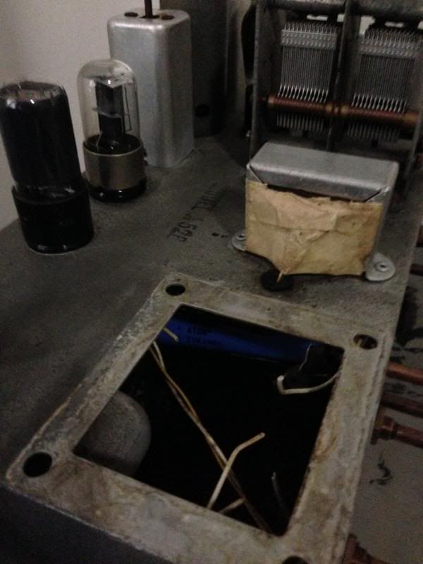
Have you tested the transformer out of circuit, ie are there any shorts to the body of the transformer or between windings? |
|
|
Return to top of page · Post #: 42 · Written at 10:56:45 AM on 1 November 2013.
|
|
|
|
Location: Somewhere, USA
Member since 22 October 2013 Member #: 1437 Postcount: 896 |
|
There was some resistance across the primary, |
|
|
Return to top of page · Post #: 43 · Written at 7:04:33 PM on 5 November 2013.
|
|
|
|
Location: Somewhere, USA
Member since 22 October 2013 Member #: 1437 Postcount: 896 |
|
I can see my own little tantrum happening there. |
|
|
Return to top of page · Post #: 44 · Written at 1:46:19 AM on 3 December 2013.
|
|
|
|
Location: Somewhere, USA
Member since 22 October 2013 Member #: 1437 Postcount: 896 |
|
The rule applied here, where the spec cap voltage is 525 Volts, |
|
|
You need to be a member to post comments on this forum.
|
|
 The power transformer makes smoke
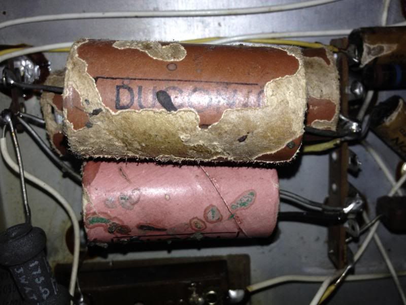
Sign In
Vintage Radio and Television is proudly brought to you by an era where things were built with pride and made to last.
DISCLAIMER: Valve radios and televisions contain voltages that can deliver lethal shocks. You should not attempt to work on a valve radio or other electrical appliances unless you know exactly what you are doing and have gained some experience with electronics and working around high voltages. The owner, administrators and staff of Vintage Radio & Television will accept no liability for any damage, injury or loss of life that comes as a result of your use or mis-use of information on this website. Please read our Safety Warning before using this website.
WARNING: Under no circumstances should you ever apply power to a vintage radio, television or other electrical appliance you have acquired without first having it checked and serviced by an experienced person. Also, at no time should any appliance be connected to an electricity supply if the power cord is damaged. If in doubt, do not apply power.
Shintara - Keepin' It Real · VileSilencer - Maintain The Rage