
Tech Talk
Forum home - Go back to Tech talk
|
AWA 429MA Champion tuning drift on warm-up
|
|
|
Return to top of page · Post #: 31 · Written at 6:20:01 PM on 27 May 2025.
|
|
|
|
Location: Belrose, NSW
Member since 31 December 2015 Member #: 1844 Postcount: 2696 |
|
630 is the same on the Northern Beaches at night, it does not have a clear channel like 702 does. |
|
|
Return to top of page · Post #: 32 · Written at 8:17:34 PM on 27 May 2025.
|
|

|
Location: Hill Top, NSW
Member since 18 September 2015 Member #: 1801 Postcount: 2246 |
|
When are these 429MA radios expected to arrive? I'm interested in what you find. |
|
|
Return to top of page · Post #: 33 · Written at 8:27:26 PM on 27 May 2025.
|
|
|
|
Location: NSW
Member since 10 June 2010 Member #: 681 Postcount: 1400 |
|
According to Wikipedia, on the East Coast, 630 is used by ABC News Radio Sydney, ABC Radio National Queenstown Tasmania and Townsvill Queensland. All of these might be picked up at night with a radio oriented for North-South reception. I have certainly noticed RN coming in. |
|
|
Return to top of page · Post #: 34 · Written at 8:30:54 PM on 27 May 2025.
|
|
|
|
Location: NSW
Member since 10 June 2010 Member #: 681 Postcount: 1400 |
|
One came today, the other I might get on Saturday. I'll do the two together for comparison. |
|
|
Return to top of page · Post #: 35 · Written at 6:38:34 PM on 28 May 2025.
|
|
|
|
Location: Belrose, NSW
Member since 31 December 2015 Member #: 1844 Postcount: 2696 |
|
I designed a 1 transistor audio preamp for the OP so that the audio gain of the 4 valve radio could be increased. 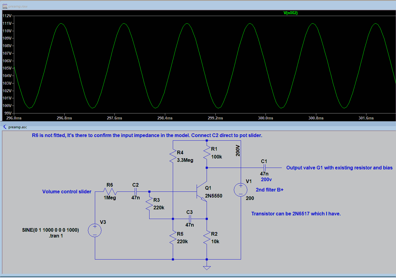 Click on image for high-resolution copy. |
|
|
Return to top of page · Post #: 36 · Written at 8:18:47 PM on 28 May 2025.
|
|
|
|
Location: NSW
Member since 10 June 2010 Member #: 681 Postcount: 1400 |
|
Thanks for going to all this trouble Ian. I could have tried something from my 1960s text book but would never have anticipated all the issues that are second nature for you. |
|
|
Return to top of page · Post #: 37 · Written at 8:43:59 PM on 28 May 2025.
|
|
|
|
Location: Hill Top, NSW
Member since 18 September 2015 Member #: 1801 Postcount: 2246 |
|
5Y3 doesn't have a separate cathode. The filament is the cathode. |
|
|
Return to top of page · Post #: 38 · Written at 9:13:47 PM on 28 May 2025.
|
|
|
|
Location: NSW
Member since 10 June 2010 Member #: 681 Postcount: 1400 |
|
Robbert of course you are right re 5Y3GT, don't know what I was thinking there! |
|
|
Return to top of page · Post #: 39 · Written at 9:25:27 PM on 28 May 2025.
|
|

|
Location: Wangaratta, VIC
Member since 21 February 2009 Member #: 438 Postcount: 5691 |
|
If you are not overly worried about originality? In my bench reformer (stepped voltage) and a dual power supply for UX-201-A (45V out of one 135V out of the other, off of a common :B" rail. Bias & heaters separate windings). I have used LR8's they red line at 450 volts. You can by altering their divider, go from 5V to 400V and even sub a burnt our choke with one. |
|
|
Return to top of page · Post #: 40 · Written at 6:48:11 AM on 29 May 2025.
|
|
|
|
Location: NSW
Member since 10 June 2010 Member #: 681 Postcount: 1400 |
|
What was I thinking there? |
|
|
Return to top of page · Post #: 41 · Written at 10:24:20 AM on 29 May 2025.
|
|
|
|
Location: Wangaratta, VIC
Member since 21 February 2009 Member #: 438 Postcount: 5691 |
|
LR8 is about the size of a small transistor. It alone would probably handle screen and grid on its own. |
|
|
Return to top of page · Post #: 42 · Written at 5:34:29 PM on 29 May 2025.
|
|
|
|
Location: Belrose, NSW
Member since 31 December 2015 Member #: 1844 Postcount: 2696 |
|
Trouble with lower voltages with that preamp is you can run out of headroom for the series voltage feedback. |
|
|
Return to top of page · Post #: 43 · Written at 7:17:31 PM on 29 May 2025.
|
|

|
Location: Hobart, TAS
Member since 31 July 2016 Member #: 1959 Postcount: 599 |
|
I recall the first I heard of "bootstrapping" was when Astor/Philips introduced their first B/W all solid state TV chassis. |
|
|
Return to top of page · Post #: 44 · Written at 8:47:18 PM on 29 May 2025.
|
|
|
|
Location: Wangaratta, VIC
Member since 21 February 2009 Member #: 438 Postcount: 5691 |
|
We all have different ideas but seeing that an LR8 is likely to cover the draw of a 6BE6, I would be inclined to interrupt its B+ rail & regulate the whole tube. With a heater rectifier there is not going to be a surge outside of its parameters. If you are working on its divider formula remember to calculate what is inside the brackets first, not incorporate anything outside, of them until you have. |
|
|
Return to top of page · Post #: 45 · Written at 11:21:58 AM on 30 May 2025.
|
|
|
|
Location: NSW
Member since 10 June 2010 Member #: 681 Postcount: 1400 |
|
We seem to be discussing two things here: |
|
|
You need to be a member to post comments on this forum.
|
|
Sign In
Vintage Radio and Television is proudly brought to you by an era where things were built with pride and made to last.
DISCLAIMER: Valve radios and televisions contain voltages that can deliver lethal shocks. You should not attempt to work on a valve radio or other electrical appliances unless you know exactly what you are doing and have gained some experience with electronics and working around high voltages. The owner, administrators and staff of Vintage Radio & Television will accept no liability for any damage, injury or loss of life that comes as a result of your use or mis-use of information on this website. Please read our Safety Warning before using this website.
WARNING: Under no circumstances should you ever apply power to a vintage radio, television or other electrical appliance you have acquired without first having it checked and serviced by an experienced person. Also, at no time should any appliance be connected to an electricity supply if the power cord is damaged. If in doubt, do not apply power.
Shintara - Keepin' It Real · VileSilencer - Maintain The Rage