Tech Talk
Forum home - Go back to Tech talk
|
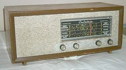
Calstan model 607 circuit details
|
|
|
Return to top of page · Post #: 16 · Written at 1:21:24 PM on 6 April 2019.
|
|
|
|
Location: Cargo, NSW
Member since 19 June 2018 Member #: 2256 Postcount: 96 |
|
Fred |
|
|
Return to top of page · Post #: 17 · Written at 6:34:55 PM on 6 April 2019.
|
|
|
|
Location: Hill Top, NSW
Member since 18 September 2015 Member #: 1801 Postcount: 2193 |
|
Mine uses the diode section of the 6N8 for demodulation and not the diodes in the 6AV6. |
|
|
Return to top of page · Post #: 18 · Written at 4:30:28 AM on 7 April 2019.
|
|
|
|
Location: Oradell, US
Member since 2 April 2010 Member #: 643 Postcount: 835 |
|
I have the transistorized version |
|
|
Return to top of page · Post #: 19 · Written at 6:21:38 AM on 7 April 2019.
|
|
|
|
Location: Toongabbie, NSW
Member since 19 November 2015 Member #: 1828 Postcount: 1379 |
|
Hi Robbert, I love hotting things up too! |
|
|
Return to top of page · Post #: 20 · Written at 7:41:13 AM on 7 April 2019.
|
|
|
|
Location: Hill Top, NSW
Member since 18 September 2015 Member #: 1801 Postcount: 2193 |
|
The 6AV6 is a high-gain triode with a gain of 100, like the old 6B6G which preceded it. I guess if you wanted lower gain, which might give smoother volume control action, you try a 6AT6 which is plugin-compatible. Of course there's probably another dozen different valve types that can be plugged in safely. One could even try out the various types to find which seems best. |
|
|
Return to top of page · Post #: 21 · Written at 8:53:02 AM on 7 April 2019.
|
|
|
|
Location: Wangaratta, VIC
Member since 21 February 2009 Member #: 438 Postcount: 5595 |
|
There seems to be a lot of same valves hidden in others. If one refers to the valve data it can be very interesting. I am of the opinion that 6M5 appears in other valves and 6CK6, is a 6M5 with the suppressor grid connected to pin 6 instead of internally to the cathode as in 6M5. |
|
|
Return to top of page · Post #: 22 · Written at 11:36:08 AM on 7 April 2019.
|
|
|
|
Location: Toongabbie, NSW
Member since 19 November 2015 Member #: 1828 Postcount: 1379 |
|
In that under chassis shot I realised I can see two strategically placed tin plate shields, one between two coils and one about the IF stage. |
|
|
Return to top of page · Post #: 23 · Written at 6:25:16 PM on 7 April 2019.
|
|
|
|
Location: Wangaratta, VIC
Member since 21 February 2009 Member #: 438 Postcount: 5595 |
|
I have indeed mentioned some of the horror stories that invariably arise when you have seen a lot of radios. It is true that many were made for a price in a competitive market. It is no different now, lots of people buy on price, often without a lot of choice. |
|
|
Return to top of page · Post #: 24 · Written at 2:07:30 PM on 29 April 2019.
|
|
|
|
Location: Cargo, NSW
Member since 19 June 2018 Member #: 2256 Postcount: 96 |
|
Have finally traced out the circuit of the radio. It is different to the circuit of your radio Fred. |
|
|
Return to top of page · Post #: 25 · Written at 2:50:24 AM on 30 April 2019.
|
|
|
|
Administrator
Location: Naremburn, NSW
Member since 15 November 2005 Member #: 1 Postcount: 7548 |
|
Document uploaded to Post 24. ‾‾‾‾‾‾‾‾‾‾‾‾‾‾‾‾‾‾‾‾‾‾‾‾‾‾‾‾‾‾‾‾‾‾‾‾‾‾‾‾‾‾‾‾‾‾‾‾‾‾‾‾‾‾‾‾‾‾‾‾‾‾‾‾‾‾‾‾ A valve a day keeps the transistor away... |
|
|
Return to top of page · Post #: 26 · Written at 8:06:38 AM on 30 April 2019.
|
|
|
|
Location: Toongabbie, NSW
Member since 19 November 2015 Member #: 1828 Postcount: 1379 |
|
Hi Norm, I like hand drawn circuits, always a bit more personal that cad drafting! |
|
|
Return to top of page · Post #: 27 · Written at 12:12:49 PM on 30 April 2019.
|
|
|
|
Location: Cargo, NSW
Member since 19 June 2018 Member #: 2256 Postcount: 96 |
|
Thanks Brad for uploading circuit diagram. |
|
|
Return to top of page · Post #: 28 · Written at 5:57:07 PM on 30 April 2019.
|
|

|
Location: Sydney, NSW
Member since 26 April 2019 Member #: 2349 Postcount: 18 |
|
Nice job tracing the circuit. |
|
|
Return to top of page · Post #: 29 · Written at 6:38:09 PM on 30 April 2019.
|
|
|
|
Location: Cargo, NSW
Member since 19 June 2018 Member #: 2256 Postcount: 96 |
|
Hi Wirelessfan |
|
|
Return to top of page · Post #: 30 · Written at 11:51:00 PM on 30 April 2019.
|
|
|
|
Location: Wangaratta, VIC
Member since 21 February 2009 Member #: 438 Postcount: 5595 |
|
Not a great fan of fuses mains side. I have noted before a Thorn that arrived here with a fused transformer. As the mains side did not overload the only damage the fuse suffered was to its holder: Waste of space. |
|
|
You need to be a member to post comments on this forum.
|
|

Sign In

Vintage Radio and Television is proudly brought to you by an era where things were built with pride and made to last.
DISCLAIMER: Valve radios and televisions contain voltages that can deliver lethal shocks. You should not attempt to work on a valve radio or other electrical appliances unless you know exactly what you are doing and have gained some experience with electronics and working around high voltages. The owner, administrators and staff of Vintage Radio & Television will accept no liability for any damage, injury or loss of life that comes as a result of your use or mis-use of information on this website. Please read our Safety Warning before using this website.
WARNING: Under no circumstances should you ever apply power to a vintage radio, television or other electrical appliance you have acquired without first having it checked and serviced by an experienced person. Also, at no time should any appliance be connected to an electricity supply if the power cord is damaged. If in doubt, do not apply power.
Shintara - Keepin' It Real · VileSilencer - Maintain The Rage


