AWA car radio
|
|
|
|
Location: Belrose, NSW
Member since 31 December 2015
Member #: 1844
Postcount: 2476
|
What you are referring to as the "main" valve is the rectifier for the 200 volts approx B+ voltage.
The 6V6 is the large black valve in the main box and I think I see a speaker transformer there.
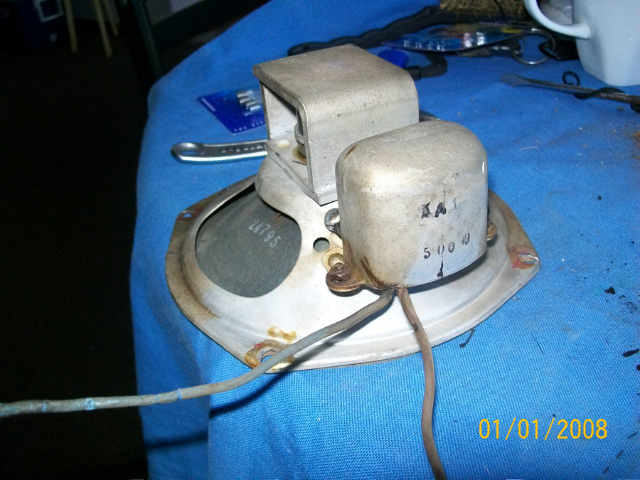
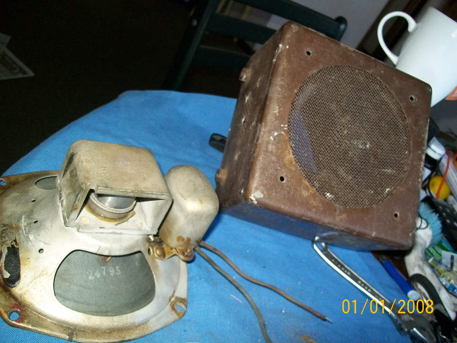
Just above the 6V6 is a socket.It should have a couple of wires that find their way back to the speaker transformer - that's in the gold-painted metal can to the right of the 6V6 in the picture.
If I am right, you should be able to connect a speaker to the two wires on that connector and hear something.
But I would caution you to check the following first:
The socket that holds the 6X5 will have two wires coming from it that go into a transformer. Find these two wires and tell me what else is connected to them. Some close-up pics may help. There should be a special capacitor there. If not, or if it is damaged, running the radio will permanently damage the vibrator transformer which cannot be replaced. This is very important. If you need to replace this capacitor I can help with sourcing a suitable part. You cannot use just any ordinary capacitor here.
I used to fix these radios many years ago for the service station that was across the road from where I grew up in the early 1960s. I remember them well. Truck drivers were fussy customers, they demanded the best performance from their radios for the long interstate runs. Good installation of the radios was important for this.
|
|
|
|
Location: Sale, VIC
Member since 20 October 2016
Member #: 1990
Postcount: 62
|
Hi IR
I have had a quick look for the first few things you mentioned. There is no transformer in the primary radio, only in the secondary booster/amp. The gold can has three wires, a main heavy common earth strap, and two normals, one going to the back of the 6v6, the other going to the on/off. I haven't tried a speaker touch. I thought the can might be a small transformer, but not sure.
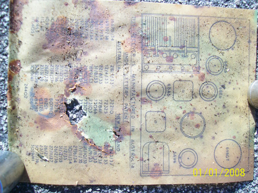
Yesterday, I noticed I had misremembered the patent dates. They are more like 1933/41.
Also, I sent some photos to Admin for posting on both my threads, but it seems people werent in today. I'm happy to do close ups IR, just point me where.
|
|
|
|
Location: Belrose, NSW
Member since 31 December 2015
Member #: 1844
Postcount: 2476
|
OK. Trace the wires that come from pins 3 and 4 of the 6V6. They will end up on the primary of the speaker transformer.
Do you know how to count the pins? Looking underneath, clockwise from the keyway on the spigot of the 6V6 base.
Please remember what I said about the 6X5 and the capacitor, it should be connected between pins 3 and 5 of the 6X5.
I suspect I see some corrosion on the vibrator transformer winding, it might already be too late to save it. To check, measure the resistance between pins 3 and 5 of the 6X5. And tell me what you find. Could be anywhere from 10 ohms to 100 ohms depending on the design of the transformer.
You should do the same with pins 3 and 4 of the 6V6. If there is a transformer in circuit, it will measure about 200 or 300 ohms (not to be confused with its impedance value).
I have a vague recollection that some AWA car radios of the period had the transformer on the speaker, I could be wrong.
|
|
|
|
Location: Sale, VIC
Member since 20 October 2016
Member #: 1990
Postcount: 62
|
Thanks IR
Ok, pins 3/4 on the 6v6 run to as follows> one wire goes into the booster harness (ie to the secondary unit), two
other wires on 4 go to three little black barrels. The two larger ones are cracked, the smaller one is .02pf 600v
seems ok and holds one wire from 6v6.
The booster.
Yes there is some mess and corrosion, but perhaps salvagable. The black barrels here too are cracked, so we can
assume they all are. I measured the ohms-r between 3/5 of the 6x5, it is> 0.96 on the 20kilohm setting. There is a
sqare item (cap?) there between. For the 6v6 I cant get a reading on pins 3/4, other spots give readings.
Of the two, the radio is in better shape than the booster.
|
|
|
|
Location: Sale, VIC
Member since 20 October 2016
Member #: 1990
Postcount: 62
|
Marcc wrote:
"The big round black caps will have to go along with every electrolytic cap. You will note a crack in the jacket of one. They often go short when that happens. The black rectangular ones are ones that I have never had to replace.
There is a buffer cap on the Vibrator and they were notorious for punching through. These have / should have a very high voltage rating 1kV or more, I often use line caps but do not go below the voltage of what is there, or recommended. Due to the spikes developed I will use the same 630V, Non Polarised axial caps as used in the rest of it.
The vibrator circuit is a tuned circuit, the buffer cap value is critical. Watch out for deteriorated rubber wire & that set has been got at as it has a "Styroseal" cap (the clear one near the tuning gang)"
...
I dont know the tech terms fully but am catching up with peoples help here. So I'm calling the barrels as Marcs black caps. Next will need to be a check of the electrolytic caps. The ones in the booster are the paper covered ones. These came off and I found they are a tin can underneath.
Im sure (and hope) this thing is salvageable.
|
|
|
|
Location: Melbourne, VIC
Member since 20 September 2011
Member #: 1009
Postcount: 1208
|
|
|
|
|
Location: Wangaratta, VIC
Member since 21 February 2009
Member #: 438
Postcount: 5389
|
What you have in this are two separate entities. The radio part & the power supply part. The power supply is of the vibrator type & this all belongs on the primary side of the transformer that provides the HV for the "B" voltage applied to the valves.
Early car radio's faced a few issues, spikes of around 200V plus created by Kettering ignitions, spikes from generators, & similar spikes from the vibrator, which is why the HV caps.
I would not mess with the Orange covered Ducon caps. Just take the voltage rating of them & replace. NB they have polarity. It is unlikely that they are still good and I would not power with any like it still in there.
|
|
|
|
Location: Sale, VIC
Member since 20 October 2016
Member #: 1990
Postcount: 62
|
MTV
It only worked on 12v, I started with lower voltages. I might be a dill but can someone tell me what the vibrator is. Is that the thing in the booster/amp with the goo oozing out of it? If so, there are no markings on it visible.
Marcc I only see one orange object, the paper covered one. Are you saying the big transformer in the remote object/speaker box (what I call the amp) is to drive the radio from external?
Can people clarify please.
Cheers.
|
|
|
|
Location: Sale, VIC
Member since 20 October 2016
Member #: 1990
Postcount: 62
|
Confirmed: the transformer in the amp is stamped 12V.
The amp is connected to the main radio by 4 wires, one is a heavy common earth strap, the other three can only be a sort of signal wire sending to the rest of the caps etc for boost. I'm guessing the 'vibrator' is a kind of oscillator, hertz reg, onoff thing. Do people know our brains are hertz regulated?
Anyway, I think IR has a handle on this. But I'm just following leads.
Cheers
|
|
|
|
Location: Wangaratta, VIC
Member since 21 February 2009
Member #: 438
Postcount: 5389
|
We have thrown ourselves in the "deep end" haven't we...........
The Vibrator thing is actually the mechanical equivalent of an Electronic Multi-Vibrator using two transistors & that's often what is in some that replace the mechanical ones. Switch Mode power supplies often have a similar front end upping the frequency.
The vibrator produces a square wave (off / on) often at a rate around 150Hz and that is what the primary of the transformer gets. Basically DC to AC. The higher the frequency the more efficient & you can then use a smaller transformer. Its sole purpose is to provide "B" voltage.
There may only be one electrolytic (That Ducon). Be that as it may get rid of it. The valve heaters will be run on DC directly from the battery.if it's 6V they will be parallel; Otherwise paired for 12V.
If you think to much & get into the heavy theory; the brain hertz.
|
|
|
|
Location: Sale, VIC
Member since 20 October 2016
Member #: 1990
Postcount: 62
|
Hehe
In the booster: Electrolytic converters x 2 (paper covered)
16MFD.525 P.V
Type
51 - 126 - 3
They are hooked up as follows> One is wired from the back of the choke coupled to the wire IR asked me to trace; the goes earth. The other EC is earthed, then is wired to the transformer.
Soon we will have a parts list.
So, are we working on the booster/amp or not? And is the 'vibrator' the actual name of the component I call silo?
it hertz not knowing
|
|
|
|
Location: Melbourne, VIC
Member since 20 September 2011
Member #: 1009
Postcount: 1208
|
If it is 12 volt it will be either a 904A or 906A. The differences between the two is that the 906A doesn't have a tone control.
Have you checked the link to the schematic in my previous post?
|
|
|
|
Location: Sale, VIC
Member since 20 October 2016
Member #: 1990
Postcount: 62
|
I have now MTV.
This radio has a tone swivel in the on/off pot. And -i just got the lids- upon them is stamped 12v, and the ID> E30020. And on the inside a little green licensing label No>125784, Its 95% intact.
I cant see any ID numbers on the trans other than the 12v stamp. There is a minimum of 6 connections to on/off pot. The schematic seems wrong.
So, 94A?
|
|
|
|
Location: Sale, VIC
Member since 20 October 2016
Member #: 1990
Postcount: 62
|
On the booster
If we look at the speaker, there is an ID: BH9, just above right of it is a number which is AG2.. possibly AG25
(needs to be AG25), making it more likey the set is a 902A. The speaker trans is an XA1. The secondary external
speaker plug, although wired differently is listed according to the diagram as being exclusively for the 904A. The
vibrator is correct with four wires, but no visible ID. It can only be a 12v-V5123. The 6x5 is correct with 6
connections with room for more. The trans is correct with 7 connections. I counted 13 other components like caps and resists, the diagram lists 17.
|
|
|
|
Location: Sale, VIC
Member since 20 October 2016
Member #: 1990
Postcount: 62
|
Hey folks
I haven't had a reply for days.
|
|
|
You need to be a member to post comments on this forum.
|