Tech Talk
Forum home - Go back to Tech talk
|
What's this radio
|
|
|
Return to top of page · Post #: 16 · Written at 8:48:53 AM on 4 February 2017.
|
|
|
|
Location: Toongabbie, NSW
Member since 19 November 2015 Member #: 1828 Postcount: 1345 |
|
Good for you, take note of what Marcc says he does this stuff all the time. |
|
|
Return to top of page · Post #: 17 · Written at 10:50:44 AM on 4 February 2017.
|
|
|
|
Location: Latham, ACT
Member since 21 February 2015 Member #: 1705 Postcount: 2198 |
|
Yes I agree Fred . The old power wire always needs to go . This baby is really firing me up. |
|
|
Return to top of page · Post #: 18 · Written at 1:11:24 PM on 4 February 2017.
|
|
|
|
Location: Latham, ACT
Member since 21 February 2015 Member #: 1705 Postcount: 2198 |
|
Ok I have done a continuity test on the transformer and all is good. It pumps out 380 volts to the rectifier and 8 volts to the heater circuit which is a little too high as the dial bulb keeps blowing. Would the answer to this be to connect a resistor to bring it down to 6 volts. And what value resister would I need to look at. |
|
|
Return to top of page · Post #: 19 · Written at 4:26:12 PM on 4 February 2017.
|
|
|
|
Location: Hobart, TAS
Member since 31 July 2016 Member #: 1959 Postcount: 575 |
|
Something wrong there. |
|
|
Return to top of page · Post #: 20 · Written at 8:06:53 PM on 4 February 2017.
|
|
|
|
Location: Latham, ACT
Member since 21 February 2015 Member #: 1705 Postcount: 2198 |
|
It's all good now. Its fun chasing other people's faults lol (not). I have replaced the flaking insulation from the heater taps and found one of the existing electros installed backwards. All voltages are NOW correct but the speaker is rats&!t and so is the speaker tranny so I have to replace the field coil and the speaker transformer and speaker. Then it should work lol. I am told a 10k resister should do the job or a choke. |
|
|
Return to top of page · Post #: 21 · Written at 8:42:53 PM on 4 February 2017.
|
|
|
|
Location: Wangaratta, VIC
Member since 21 February 2009 Member #: 438 Postcount: 5488 |
|
How can all of the voltages be correct and the speaker tranny be RS. If the speaker transformer has an open primary the voltages will be high and you risk wiping out the screen if it's a Pentode: It will have little voltage on the plate with an open transformer. If the heavy windings on the outside are exposed & not damaged, it's likely not broke. The wrap over bracket will come off & the bobbin can be taken out. |
|
|
Return to top of page · Post #: 22 · Written at 9:49:44 PM on 4 February 2017.
|
|
|
|
Location: Latham, ACT
Member since 21 February 2015 Member #: 1705 Postcount: 2198 |
|
The tech that's been teaching me has gone right over it. The speaker transformer is definitely open circuit and the speaker itself is rusted and frozen solid. I will be replacing the speaker and transformer. Thanks Marcc for letting me know the resistor or choke value. Once I get those issues sorted there may be more but hopefully not. We are both of the opinion that this radio never worked because the initial builder has really made some stuffups. 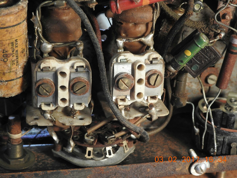 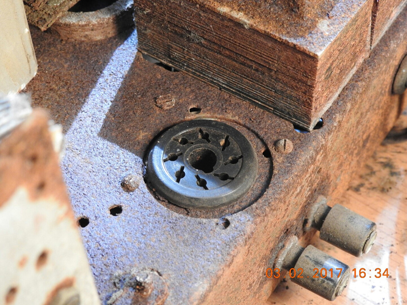 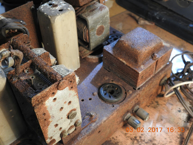 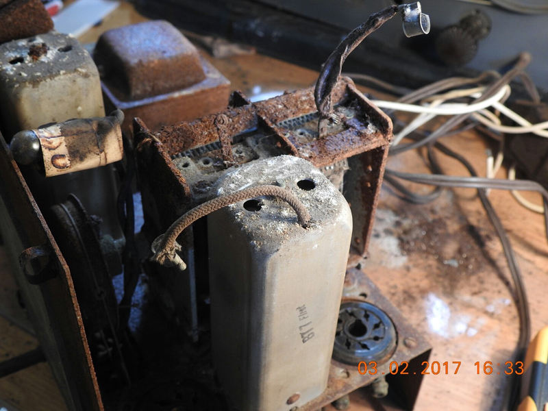 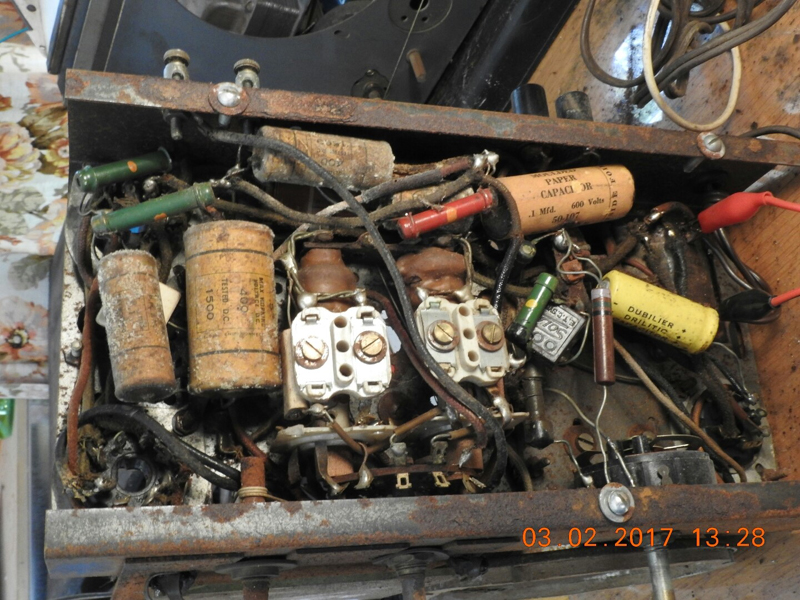 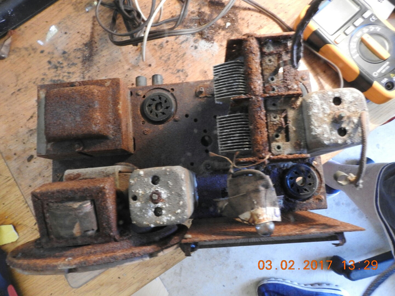 |
|
|
Return to top of page · Post #: 23 · Written at 10:33:11 PM on 4 February 2017.
|
|
|
|
Administrator
Location: Naremburn, NSW
Member since 15 November 2005 Member #: 1 Postcount: 7473 |
|
Supplementary photos added to Post 22. ‾‾‾‾‾‾‾‾‾‾‾‾‾‾‾‾‾‾‾‾‾‾‾‾‾‾‾‾‾‾‾‾‾‾‾‾‾‾‾‾‾‾‾‾‾‾‾‾‾‾‾‾‾‾‾‾‾‾‾‾‾‾‾‾‾‾‾‾ A valve a day keeps the transistor away... |
|
|
Return to top of page · Post #: 24 · Written at 11:46:32 AM on 6 February 2017.
|
|
|
|
Location: Belrose, NSW
Member since 31 December 2015 Member #: 1844 Postcount: 2544 |
|
"We are both of the opinion that this radio never worked because the initial builder has really made some stuffups." |
|
|
Return to top of page · Post #: 25 · Written at 12:28:56 PM on 6 February 2017.
|
|
|
|
Location: Hobart, TAS
Member since 31 July 2016 Member #: 1959 Postcount: 575 |
|
Well spotted Ian. |
|
|
Return to top of page · Post #: 26 · Written at 1:27:25 PM on 6 February 2017.
|
|
|
|
Location: Kempsey, NSW
Member since 6 December 2016 Member #: 2019 Postcount: 37 |
|
Hi everyone, |
|
|
Return to top of page · Post #: 27 · Written at 1:50:59 PM on 6 February 2017.
|
|
|
|
Location: Sydney, NSW
Member since 28 January 2011 Member #: 823 Postcount: 6824 |
|
Would you be referring to actual molasses to treat the rust on the chassis as well as other components? |
|
|
Return to top of page · Post #: 28 · Written at 4:41:27 PM on 6 February 2017.
|
|
|
|
Location: Latham, ACT
Member since 21 February 2015 Member #: 1705 Postcount: 2198 |
|
There may have been plenty of to and throw with the knobs but I can assure you that it was impossible that it worked. Some of the original caps ( electros)were in backwards. Children could have been playing with it. The fellow teaching me is a professional tech that used to work for Reliance Radio. |
|
|
Return to top of page · Post #: 29 · Written at 8:53:25 PM on 6 February 2017.
|
|
|
|
Location: Belrose, NSW
Member since 31 December 2015 Member #: 1844 Postcount: 2544 |
|
Tallar, I've had a close look at the pictures and traced a few things. Enough to draw you a circuit. |
|
|
Return to top of page · Post #: 30 · Written at 7:26:29 AM on 7 February 2017.
|
|
|
|
Location: Latham, ACT
Member since 21 February 2015 Member #: 1705 Postcount: 2198 |
|
The Electro that was wired in backwards is actually not visible in those photos. It's buried under everything in the 2nd last photo top left near the antenna and earth terminals. The paper cap you can see running alongside the rear of the chassis is terminated to either side of the electro which is underneath. |
|
|
You need to be a member to post comments on this forum.
|
|

Sign In

Vintage Radio and Television is proudly brought to you by an era where things were built with pride and made to last.
DISCLAIMER: Valve radios and televisions contain voltages that can deliver lethal shocks. You should not attempt to work on a valve radio or other electrical appliances unless you know exactly what you are doing and have gained some experience with electronics and working around high voltages. The owner, administrators and staff of Vintage Radio & Television will accept no liability for any damage, injury or loss of life that comes as a result of your use or mis-use of information on this website. Please read our Safety Warning before using this website.
WARNING: Under no circumstances should you ever apply power to a vintage radio, television or other electrical appliance you have acquired without first having it checked and serviced by an experienced person. Also, at no time should any appliance be connected to an electricity supply if the power cord is damaged. If in doubt, do not apply power.
Shintara - Keepin' It Real · VileSilencer - Maintain The Rage

