
Tech Talk
Forum home - Go back to Tech talk
|
Nameless 1938 Ozzie Radio
|
|
|
Return to top of page · Post #: 16 · Written at 8:59:25 AM on 24 December 2014.
|
|

|
Location: Brisbane, QLD
Member since 22 December 2014 Member #: 1672 Postcount: 13 |
|
Brad...what a memory!! Yes same escutcheon as the one on your thread and U tube. Unfortunately , I could not see the printing clearly on the dial glass but certainly the same manufacturer of both dial assemblies, even though my dial drive has not got dial lights both sides. 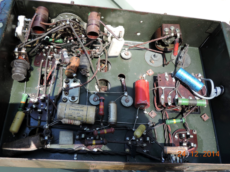 It has rheostat volume control that appears to have about 100v applied to it. Prior to my vintage. Not something I ever worked on just a vague memory. Marc, I don't have access to a valve tester , so it's power up and measure voltages and hope! I have recapped the 6D6 (IF) and it seems ok.??? If I can file a bit of glass back I may revive the 6A7 (RF) but not holding my breath , also you will note that it's plate resistor (from memory) has been cooking at some stage so don't hold much hope for it. Off to my shed with camera. Thanks all, Gary |
|
|
Return to top of page · Post #: 17 · Written at 10:05:03 AM on 24 December 2014.
|
|
|
Location: Melbourne, VIC
Member since 20 September 2011 Member #: 1009 Postcount: 1270 |
|
I've just found a 1938 ad for a "Velco" battery kit-set. Apart from being a battery set, the chassis and the dial/escutcheon look the same as the one in this thread. 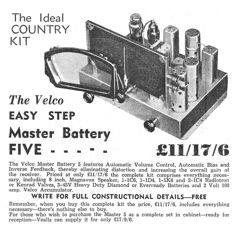 "Velco" is the brand name for Arthur J. Veall, who was a large radio and electrical retailer in Melbourne. Veall's was represented in Queensland by a B. Martin of Charlotte St., Brisbane. I still wont call this radio as being a "Velco" as I believe this style of dial/escutcheon was used in many generic radios made around 1938. As for a road map, I'd first look at the 1938 Weldon 3/38D that was mentioned by GTC. The other radios mentioned seem a bit too early. There is a faded ARTS&P label on the bottom right hand corner of the chassis. Are you able to make out any large letters such as a D, E or F.? This will indicate year of manufacture - for example E = 1938. |
|
|
Return to top of page · Post #: 18 · Written at 8:35:07 AM on 25 December 2014.
|
|
|
|
Location: Brisbane, QLD
Member since 22 December 2014 Member #: 1672 Postcount: 13 |
|
The chassis above has all the hallmarks of mine, Same factory, but different component layout. |
|
|
Return to top of page · Post #: 19 · Written at 9:27:25 AM on 25 December 2014.
|
|

|
Location: Wangaratta, VIC
Member since 21 February 2009 Member #: 438 Postcount: 5749 |
|
Bearing in mind I do the odd commercial repair. I would get rid of every wax paper cap in it and I will not use electrolytics below 500V on an 80 / 5Y3 and similar filament rectifiers. |
|
|
Return to top of page · Post #: 20 · Written at 10:55:30 AM on 26 December 2014.
|
|
|
|
Location: Brisbane, QLD
Member since 22 December 2014 Member #: 1672 Postcount: 13 |
|
Thanks to the leads from Brad, Monochrome, et al. , I now have a blurry thumbnail circuit of the Weldon 3/38D. (found on Radiomuseum) |
|
|
Return to top of page · Post #: 21 · Written at 4:41:13 PM on 26 December 2014.
|
|
|
|
Location: Melbourne, VIC
Member since 20 September 2011 Member #: 1009 Postcount: 1270 |
|
Here is a better quality pdf circuit of the Weldon 3/38D. |
|
|
Return to top of page · Post #: 22 · Written at 8:23:33 PM on 26 December 2014.
|
|
|
|
Location: Wangaratta, VIC
Member since 21 February 2009 Member #: 438 Postcount: 5749 |
|
Its pretty obvious why there is 100V on the pot. If there is a tangle Its cactus & a 5K WW from RS is on the list. Buy 630V Axial caps, I do not like the length, but use in places the red Greencaps. |
|
|
Return to top of page · Post #: 23 · Written at 8:17:59 AM on 27 December 2014.
|
|
|
|
Location: Brisbane, QLD
Member since 22 December 2014 Member #: 1672 Postcount: 13 |
|
Monochrome, In your debt again ! Thanks mate. |
|
|
Return to top of page · Post #: 24 · Written at 11:33:25 AM on 27 December 2014.
|
|
|
|
Location: Wangaratta, VIC
Member since 21 February 2009 Member #: 438 Postcount: 5749 |
|
I am indicating that I think this one should be easy. |
|
|
Return to top of page · Post #: 25 · Written at 9:28:42 AM on 11 January 2015.
|
|
|
|
Location: Brisbane, QLD
Member since 22 December 2014 Member #: 1672 Postcount: 13 |
|
Back again!! |
|
|
Return to top of page · Post #: 26 · Written at 2:02:41 PM on 11 January 2015.
|
|
|
|
Location: Wangaratta, VIC
Member since 21 February 2009 Member #: 438 Postcount: 5749 |
|
http://tubedata.milbert.com/sheets/049/6/6A7S.pdf. |
|
|
Return to top of page · Post #: 27 · Written at 7:14:19 AM on 12 January 2015.
|
|
|
|
Location: Brisbane, QLD
Member since 22 December 2014 Member #: 1672 Postcount: 13 |
|
Hi Marcc, Understand precautionary principle. Nothing I could do for shorted turns in the transformer. By the look of the chassis (now repainted) I suspect it was exposed to salty air or similar. |
|
|
Return to top of page · Post #: 28 · Written at 9:55:07 PM on 12 January 2015.
|
|
|
|
Location: Wangaratta, VIC
Member since 21 February 2009 Member #: 438 Postcount: 5749 |
|
Whilst I test what valves I can, to avoid putting in shorted ones into new work, If there is 6A7 / 6A8 instability, all of the caps & resistors around it should be checked. Those valves are voltage sensitive. |
|
|
You need to be a member to post comments on this forum.
|
|

Sign In

Vintage Radio and Television is proudly brought to you by an era where things were built with pride and made to last.
DISCLAIMER: Valve radios and televisions contain voltages that can deliver lethal shocks. You should not attempt to work on a valve radio or other electrical appliances unless you know exactly what you are doing and have gained some experience with electronics and working around high voltages. The owner, administrators and staff of Vintage Radio & Television will accept no liability for any damage, injury or loss of life that comes as a result of your use or mis-use of information on this website. Please read our Safety Warning before using this website.
WARNING: Under no circumstances should you ever apply power to a vintage radio, television or other electrical appliance you have acquired without first having it checked and serviced by an experienced person. Also, at no time should any appliance be connected to an electricity supply if the power cord is damaged. If in doubt, do not apply power.
Shintara - Keepin' It Real · VileSilencer - Maintain The Rage