Tech Talk
Forum home - Go back to Tech talk
|
HMV D33A turntable info needed
|
|
|
Return to top of page · Post #: 1 · Written at 10:04:03 PM on 11 September 2017.
|
|
|
|
Location: Melbourne, VIC
Member since 26 December 2010 Member #: 794 Postcount: 396 |
|
Hi Folks, |
|
|
Return to top of page · Post #: 2 · Written at 9:37:10 AM on 12 September 2017.
|
|
|
|
Location: Wangaratta, VIC
Member since 21 February 2009 Member #: 438 Postcount: 5595 |
|
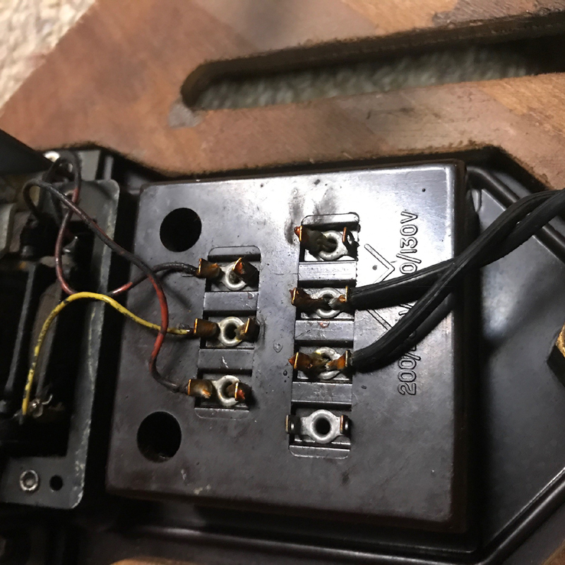
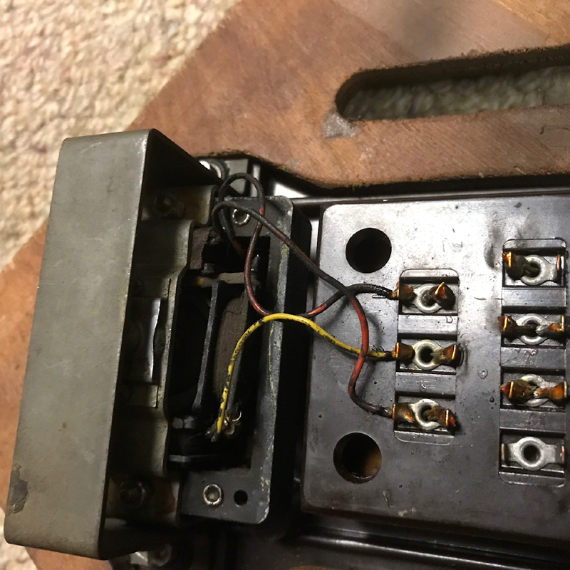
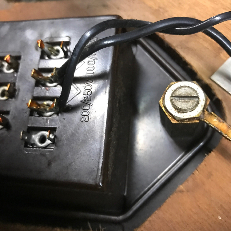
It might be an idea to see if the cap is across the mains, or one has a separate wire feeding into a different point in the motor? |
|
|
Return to top of page · Post #: 3 · Written at 4:27:03 PM on 12 September 2017.
|
|
|
|
Location: Belrose, NSW
Member since 31 December 2015 Member #: 1844 Postcount: 2628 |
|
Those old motor caps often contain carcinogenic substances so use due care, hand washing etc. |
|
|
Return to top of page · Post #: 4 · Written at 5:09:20 PM on 12 September 2017.
|
|
|
|
Location: Melbourne, VIC
Member since 26 December 2010 Member #: 794 Postcount: 396 |
|
Thanks guys, I'll post a couple of pics |
|
|
Return to top of page · Post #: 5 · Written at 8:32:15 PM on 12 September 2017.
|
|
|
|
Location: Melbourne, VIC
Member since 26 December 2010 Member #: 794 Postcount: 396 |
|
Hi again,     |
|
|
Return to top of page · Post #: 6 · Written at 3:03:20 AM on 13 September 2017.
|
|
|
|
Location: Belrose, NSW
Member since 31 December 2015 Member #: 1844 Postcount: 2628 |
|
Have you lubed the motor bearings and filed down the surface of the rubber wheel (using the motor to turn it) so that the surface glaze is removed? |
|
|
Return to top of page · Post #: 7 · Written at 7:27:45 AM on 13 September 2017.
|
|
|
|
Location: Melbourne, VIC
Member since 26 December 2010 Member #: 794 Postcount: 396 |
|
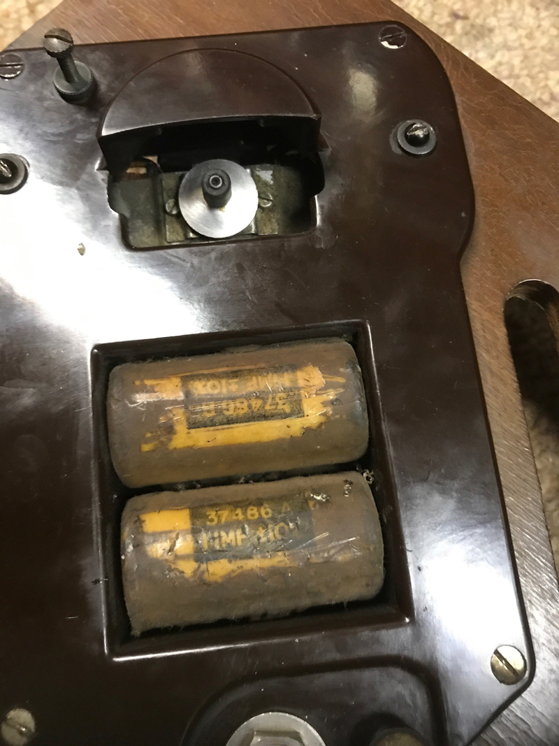
Hi Ian, yes al the above has been done. The motor was originally seized and is fine now. It's definitely an issue when the motor is under load. I suspect it is the caps but it's hard to read their values given the age of them.... they look like 1.1mf but hopefully someone here will know and I'll replace them. |
|
|
Return to top of page · Post #: 8 · Written at 8:38:55 AM on 13 September 2017.
|
|
|
|
Location: Albury, NSW
Member since 1 May 2016 Member #: 1919 Postcount: 2048 |
|
Most early turntable motors similar to the early Garrard, have what is called a floating self lubricating bearing that works on the same principle as a ball joint. |
|
|
Return to top of page · Post #: 9 · Written at 7:53:37 PM on 13 September 2017.
|
|
|
|
Location: Melbourne, VIC
Member since 26 December 2010 Member #: 794 Postcount: 396 |
|
Hi Pete, |
|
|
Return to top of page · Post #: 10 · Written at 9:03:54 PM on 13 September 2017.
|
|
|
|
Administrator
Location: Naremburn, NSW
Member since 15 November 2005 Member #: 1 Postcount: 7548 |
|
Photos uploaded to Post 5. ‾‾‾‾‾‾‾‾‾‾‾‾‾‾‾‾‾‾‾‾‾‾‾‾‾‾‾‾‾‾‾‾‾‾‾‾‾‾‾‾‾‾‾‾‾‾‾‾‾‾‾‾‾‾‾‾‾‾‾‾‾‾‾‾‾‾‾‾ A valve a day keeps the transistor away... |
|
|
Return to top of page · Post #: 11 · Written at 9:14:12 PM on 13 September 2017.
|
|
|
|
Location: Sydney, NSW
Member since 28 January 2011 Member #: 823 Postcount: 6882 |
|
I can't quite make out the labels on those caps, other than "11(?) MF +/-10%" so it seems the answer is there if you can read it clearly. |
|
|
Return to top of page · Post #: 12 · Written at 9:40:34 PM on 13 September 2017.
|
|
|
|
Location: Hill Top, NSW
Member since 18 September 2015 Member #: 1801 Postcount: 2193 |
|
I just scrapped a tape recorder and it had a large 2μF cap next to the motor. The cap appears to be in fine condition. |
|
|
Return to top of page · Post #: 13 · Written at 10:04:51 PM on 13 September 2017.
|
|
|
|
Location: Sydney, NSW
Member since 28 January 2011 Member #: 823 Postcount: 6882 |
|
I think you may be right about the 1.1 -- with the decimal point halfway up the 1. |
|
|
Return to top of page · Post #: 14 · Written at 10:45:18 PM on 13 September 2017.
|
|
|
|
Location: Melbourne, VIC
Member since 26 December 2010 Member #: 794 Postcount: 396 |
|
Thx guys, as to the voltage of the caps, I'm guessing minimum 250vac |
|
|
Return to top of page · Post #: 15 · Written at 10:59:00 PM on 13 September 2017.
|
|
|
|
Location: Sydney, NSW
Member since 28 January 2011 Member #: 823 Postcount: 6882 |
|
I'd say 440 or 450 volts. You need to cater for peak voltage (plus some head room), not RMS voltage. |
|
|
You need to be a member to post comments on this forum.
|
|

Sign In

Vintage Radio and Television is proudly brought to you by an era where things were built with pride and made to last.
DISCLAIMER: Valve radios and televisions contain voltages that can deliver lethal shocks. You should not attempt to work on a valve radio or other electrical appliances unless you know exactly what you are doing and have gained some experience with electronics and working around high voltages. The owner, administrators and staff of Vintage Radio & Television will accept no liability for any damage, injury or loss of life that comes as a result of your use or mis-use of information on this website. Please read our Safety Warning before using this website.
WARNING: Under no circumstances should you ever apply power to a vintage radio, television or other electrical appliance you have acquired without first having it checked and serviced by an experienced person. Also, at no time should any appliance be connected to an electricity supply if the power cord is damaged. If in doubt, do not apply power.
Shintara - Keepin' It Real · VileSilencer - Maintain The Rage
