
Tech Talk
Forum home - Go back to Tech talk
|
Old Electrolytics
|
|
|
Return to top of page · Post #: 1 · Written at 2:13:50 PM on 23 October 2013.
|
|
|
|
Location: Somewhere, USA
Member since 22 October 2013 Member #: 1437 Postcount: 896 |
|
Hi Guys, |
|
|
Return to top of page · Post #: 2 · Written at 2:40:15 PM on 23 October 2013.
|
|
|
|
Location: NSW
Member since 10 June 2010 Member #: 681 Postcount: 1379 |
|
The important numbers on the case are the capacitance value in microfarads eg 8μF, the working voltage in volts eg WV 500V, and the peak voltage eg PV 550V. |
|
|
Return to top of page · Post #: 3 · Written at 2:57:41 PM on 23 October 2013.
|
|

|
Location: Melbourne, VIC
Member since 20 September 2011 Member #: 1009 Postcount: 1257 |
Your Musicmasters is most likely a model A5, or one its variants. Circuit diagrams are available. I'm sure someone here can help you out. |
|
|
Return to top of page · Post #: 4 · Written at 3:12:47 PM on 23 October 2013.
|
|

|
Location: Tamworth, NSW
Member since 6 April 2012 Member #: 1126 Postcount: 471 |
|
Top 16μF 525v |
|
|
Return to top of page · Post #: 5 · Written at 4:09:39 PM on 23 October 2013.
|
|

|
Location: Sydney, NSW
Member since 28 January 2011 Member #: 823 Postcount: 6891 |
|
Your Musicmasters is most likely a model A5, or one its variants. Circuit diagrams are available. I'm sure someone here can help you out. |
|
|
Return to top of page · Post #: 6 · Written at 4:46:12 PM on 23 October 2013.
|
|
|
|
Location: Somewhere, USA
Member since 22 October 2013 Member #: 1437 Postcount: 896 |
|
GTC, |
|
|
Return to top of page · Post #: 7 · Written at 5:12:08 PM on 23 October 2013.
|
|
|
|
Location: Sydney, NSW
Member since 28 January 2011 Member #: 823 Postcount: 6891 |
|
The forum's default setting is email address hidden. That's to thwart address harvesters. |
|
|
Return to top of page · Post #: 8 · Written at 7:58:54 PM on 23 October 2013.
|
|

|
Administrator
Location: Naremburn, NSW
Member since 15 November 2005 Member #: 1 Postcount: 7567 |
|
The forum's default setting is email address hidden. That's to thwart address harvesters. ‾‾‾‾‾‾‾‾‾‾‾‾‾‾‾‾‾‾‾‾‾‾‾‾‾‾‾‾‾‾‾‾‾‾‾‾‾‾‾‾‾‾‾‾‾‾‾‾‾‾‾‾‾‾‾‾‾‾‾‾‾‾‾‾‾‾‾‾ A valve a day keeps the transistor away... |
|
|
Return to top of page · Post #: 9 · Written at 8:18:24 PM on 23 October 2013.
|
|
|
|
Location: Somewhere, USA
Member since 22 October 2013 Member #: 1437 Postcount: 896 |
|
That's much appreciated GTC, |
|
|
Return to top of page · Post #: 10 · Written at 8:21:36 PM on 23 October 2013.
|
|
|
|
Location: Sydney, NSW
Member since 28 January 2011 Member #: 823 Postcount: 6891 |
|
Nice gesture, but if I were you, and I was going to restore the chassis, I'd hang onto that dial glass. You then have the option of building your own case or, if an case eventually becomes available, there's the chance that the dial glass will be missing or broken. |
|
|
Return to top of page · Post #: 11 · Written at 9:46:33 PM on 23 October 2013.
|
|
|
|
Location: Somewhere, USA
Member since 22 October 2013 Member #: 1437 Postcount: 896 |
|
I would normally think that way, and be a real purist, |
|
|
Return to top of page · Post #: 12 · Written at 9:54:49 PM on 23 October 2013.
|
|
|
|
Location: Sydney, NSW
Member since 28 January 2011 Member #: 823 Postcount: 6891 |
|
Offering useful radio stuff free is a nice gesture in my book! |
|
|
Return to top of page · Post #: 13 · Written at 4:26:26 AM on 24 October 2013.
|
|
|
|
Location: Somewhere, USA
Member since 22 October 2013 Member #: 1437 Postcount: 896 |
|
I previously took down paper and electro cap values I could see, |
|
|
Return to top of page · Post #: 14 · Written at 4:21:55 PM on 26 October 2013.
|
|
|
|
Location: Somewhere, USA
Member since 22 October 2013 Member #: 1437 Postcount: 896 |
|
Just a question about the electrolytics... |
|
|
Return to top of page · Post #: 15 · Written at 7:44:25 PM on 26 October 2013.
|
|
|
|
Location: Tamworth, NSW
Member since 6 April 2012 Member #: 1126 Postcount: 471 |
|
http://www.justradios.com/cart.html. |
|
|
You need to be a member to post comments on this forum.
|
|

 Art: I have posted my suggestions as to model in your other thread.
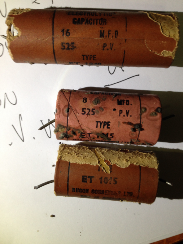
Sign In
Vintage Radio and Television is proudly brought to you by an era where things were built with pride and made to last.
DISCLAIMER: Valve radios and televisions contain voltages that can deliver lethal shocks. You should not attempt to work on a valve radio or other electrical appliances unless you know exactly what you are doing and have gained some experience with electronics and working around high voltages. The owner, administrators and staff of Vintage Radio & Television will accept no liability for any damage, injury or loss of life that comes as a result of your use or mis-use of information on this website. Please read our Safety Warning before using this website.
WARNING: Under no circumstances should you ever apply power to a vintage radio, television or other electrical appliance you have acquired without first having it checked and serviced by an experienced person. Also, at no time should any appliance be connected to an electricity supply if the power cord is damaged. If in doubt, do not apply power.
Shintara - Keepin' It Real · VileSilencer - Maintain The Rage